COPYRIGHT
©
2001 CANON INC. 2000 2000 2000 2000 CANON iR8500/7200 REV.1 AUG. 2001
CHAPTER 6 TROUBLESHOOTING
6-48
2.7.7 Replacing the DC Controller PCB
1) If possible, print out the data of user mode/service mode.
2) Replace the DC controller PCB.
3) Execute the following service mode to initialize RAM.
COPIER>FUNCTION>CLEAR>DC-CON
4) After assembling the machine, connect the power plug to the power outlet, and turn on
the power switch.
5) Enter the settings of the following from the service label:
COPIER>ADJUST>LASER (all items)
COPIER>ADJUST>DEVELOP (all items)
COPIER>ADJUST>DENS (all items)
COPIER>ADJUST>BLANK (all items)
COPIER>ADJUST>V-CONT (all items)
COPIER>ADJUST>HV-PRI (all items)
COPIER>ADJUST>HV-TR (all items)
COPIER>ADJUST>HV-SP (all items)
COPIER>ADJUST>FEED-ADJ (all items)
COPIER>ADJUST>CST-ADJ (all items)
COPIER>ADJUST>EXP-LED (all items)
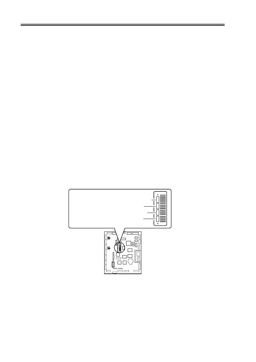
6) Enter the settings (4 types) recorded on the label attached to the new DC controller PCB
in service e mode.
F06-207-04
7) Turn off and then on the main power switch.
COPIER>ADJUST>DEVELOP>D-HV-DE
COPIER>ADJUST>HV-TR>D-HV-TR
COPIER>ADJUST>HV-TR>D-PRE-TR
COPIER>ADJUST>HV-SP>D-HV-SP
-0.6 +0.1 +0.9 -0.5

 Loading...


