COPYRIGHT
©
2001 CANON INC. 2000 2000 2000 2000 CANON iR8500/7200 REV.1 AUG. 2001
CHAPTER 6 TROUBLESHOOTING
6-34
[A]
[B]
[A]
[B]
Z
View from Z
36±0.5mm
[1]
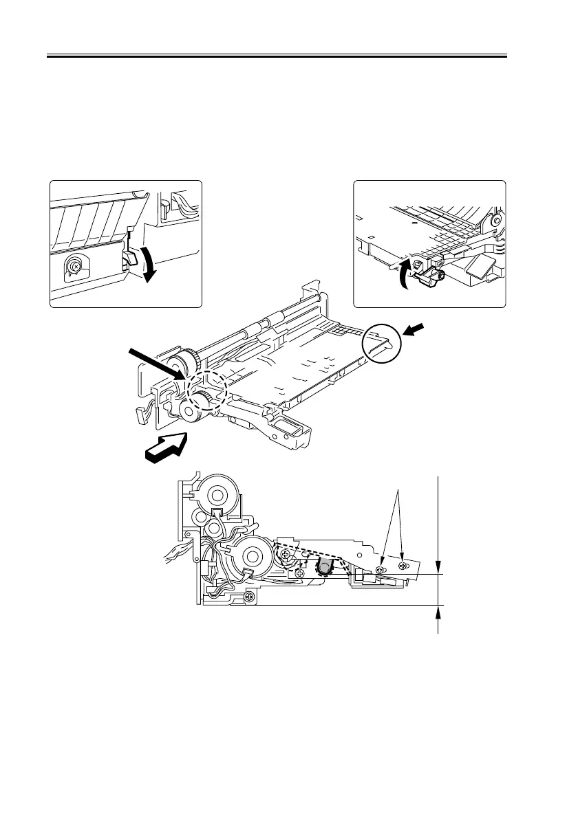
2.4.16 Position for the Cassette 3/4 Pickup Solenoid (SL9/10)
Adjust the position using the screws [1] so that when [A] and [B] in the following figure
are operated and when the plunger of the pickup roller releasing solenoid is pulled, the dis-
tance from the bottom of each pickup unit to the bottom edge of the bushing of the roller
support plate is 36 ±0.5 mm.
F06-204-20
 Loading...