COPYRIGHT
©
2001 CANON INC. 2000 2000 2000 2000 CANON iR8500/7200 REV.1 AUG. 2001
CHAPTER 6 TROUBLESHOOTING
6-105
HV-DC PCB
• J722
• J723
• J730
• J734
HV-AC PCB
• J741
• J742
4.1.20 E068
Mounting condition
1) Is the transfer/separation charging assembly mounted securely?
NO: Mount the assembly securely.
Connection
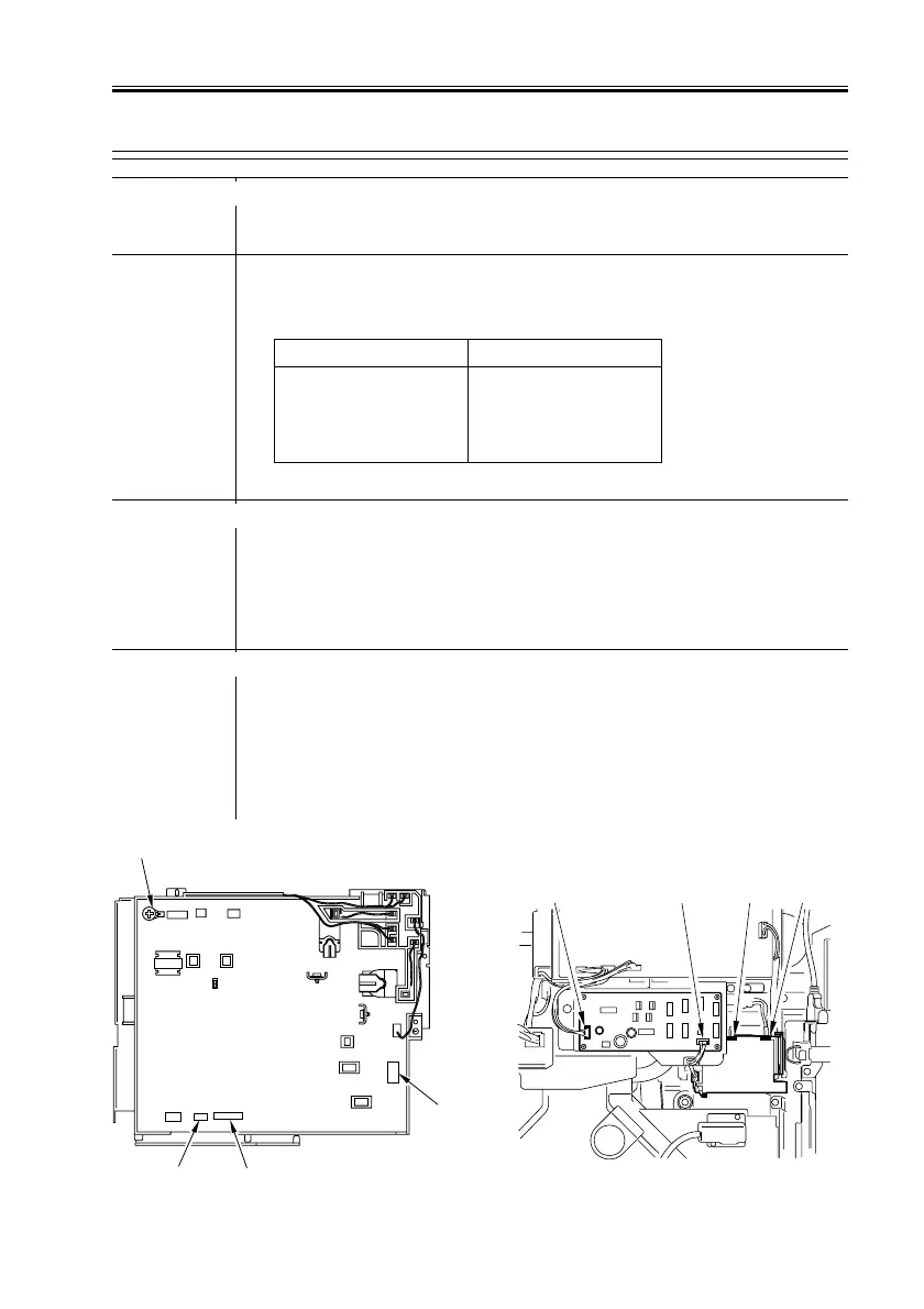
2) Are the following connectors on the HV PCB and the HV-AC PCB
normal? Further, are the screws fitted properly? (See F06-401-03.)
NO: Correct the connection.
Separation charging assembly
3) Disconnect the connector T1-S from the transformer assembly of
the HV-AC PCB, and make copies. Is E068 indicated? (See F06-
401-04.)
NO: Clean the HV-AC PCB, and make copies. If E068 is indicated, re-
place the separation charging assembly.
Pre-transfer charging assembly, HV-DC PCB
4) Disconnect the connector T1-Q from the transformer assembly of
the HV-AC PCB, and make copies. Is E068 indicated? (See F06-
401-04.)
NO: Clean the pre-transfer charging assembly, and make copies. If
E068 is indicated, replace the pre-transfer charging assembly.
YES: Replace the HV-AC PCB.
F06-401-03 F06-401-04
J722 J723
J734
J730
T1-SJ742J741 T1-Q

 Loading...


