CHAPTER 2 NEW FUNCTIONS
2-205
COPYRIGHT
©
2001 CANON INC. 2000 2000 2000 2000 CANON iR8500/7200 REV.1 AUG. 2001
10.4.4 Drive Assembly
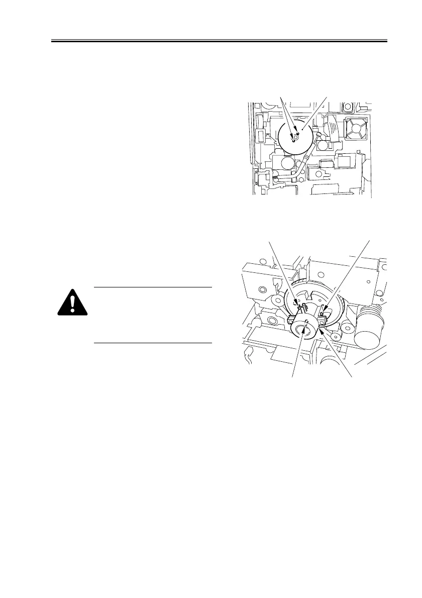
a. Removing the Drive Assembly
1) Remove the HV-DC PCB (See
10.4.7.c.).
2) Remove the 2 screws [1], and detach the
flywheel [2].
F02-1004-50
3) Loosen the 2 screws [1] (w/ hex hole),
and remove the binding screw [2] (w/
spring); then, detach the gear [3] of the
drum shaft.
When removing the screw from
the drum shaft gear, be sure to
pay attention to the direction of
gear rotation, i.e., turn it coun-
terclockwise.
F02-1004-51
[1]
[2]
[1]
[2]
[1]
[3]
 Loading...