CHAPTER 2 NEW FUNCTIONS
2-211
COPYRIGHT
©
2001 CANON INC. 2000 2000 2000 2000 CANON iR8500/7200 REV.1 AUG. 2001
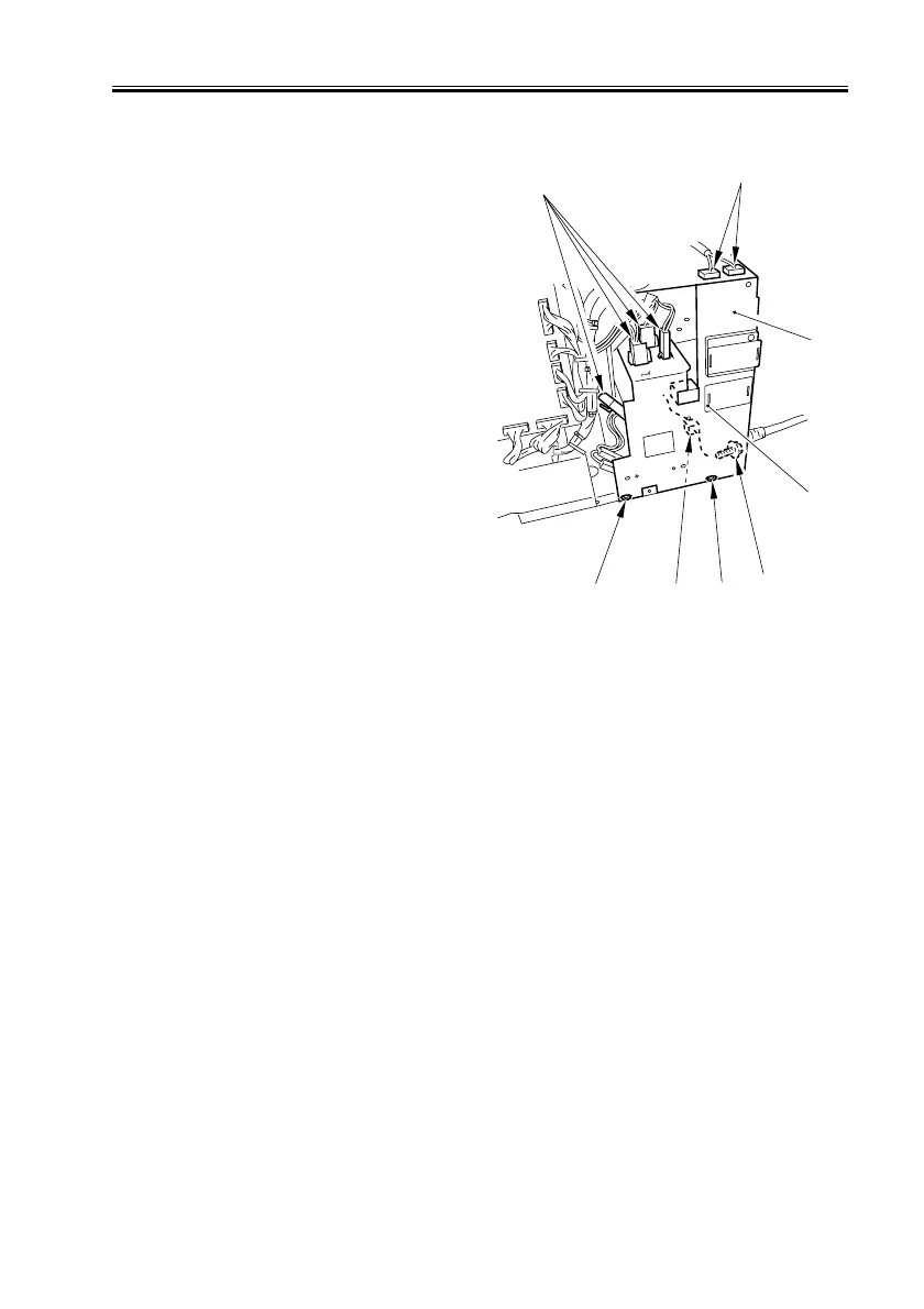
c. Removing the Drum Heater Switch Assembly
1) Remove the rear cover (See 10.4.1.e.).
2) Remove the left lower cover (4 screws).
3) Remove the 3 screws [1], and discon-
nect the 7 connectors [2]; then, de-
tached power cord base [3]. thereafter,
free the fixing claw to detach the drum
heat switch [4].
F02-1004-62
10.4.6 PCBs
For the following, see their appropriate sections:
• Transformer PCB
(2 “Original Exposure System”)
• Reader controller PCB
(2 “Original Exposure System”)
• Differential PCB
(2 “Original Exposure System”)
• Hard disk
(3 “Image Processing System”)
• Control panel controller (CPU) PCB
(10.4.2 “Control Panel”)
• Control panel inverter PCB
(10.4.2 “Control Panel”)
Control panel PCB
(10.4.2 “Control Panel”)
[2]
[2]
[2]
[1]
[1]
[1]
[3]
[4]

 Loading...


