COPYRIGHT
©
2001 CANON INC. 2000 2000 2000 2000 CANON iR8500/7200 REV.1 AUG. 2001
CHAPTER 2 NEW FUNCTIONS
2-51
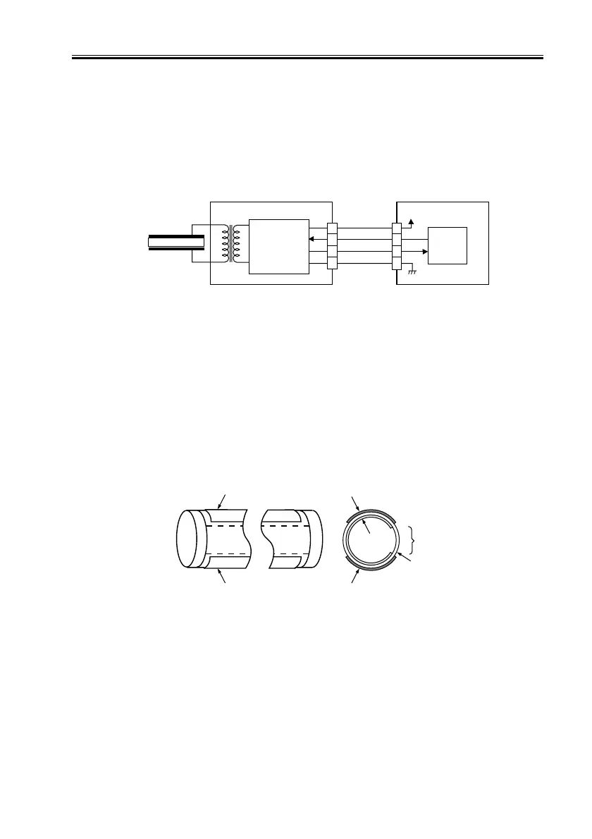
3.7 Controlling the Scanning Lamp (LA101)
3.7.1 Outline
The system used to control the scanning lamp is constructed as follows and the items of
control include the following:
[1] Turning on and off the scanning lamp.
[2] Monitoring the scanning lamp for errors.
F02-307-01
3.7.2 Scanning Lamp
The machine’s scanning lamp is a xenon lamp of a non-electrode discharge type, in which
xenon gas is sealed in a tube.
On the outside of the glass tube, two electrodes are arranged parallel to the tube axis, and
the inner side of the glass tube is coated with fluorescent material.
The internal gas discharges and, as a result, the fluorescent material glows when a high-
frequency voltage is applied across the electrodes.
F02-307-02
3.7.3 Turning On/Off the Lamp
The scanning lamp is turned on/off in response to the drive signal (LAMP_ON) from the
CPU on the reader controller PCB. When the signal is generated, the inverter generates a
high-frequency, and high-voltage using the drive voltage (+24 V) supplied by the reader
controller PCB to turn on the xenon tube.
Inverter PCB
Xenon lamp
Activation
control
circuit
J5101
J5007
+24V
Reader controller
PCB
1
3
4
2
5
3
2
4
LAMP_ON
INV_ERR
LA2
CPU
Fluorescent
material
Electrode
Opening
Electrode
ElectrodeElectrode
Glass tube

 Loading...


