CHAPTER 2 NEW FUNCTIONS
2-176
COPYRIGHT
©
2001 CANON INC. 2000 2000 2000 2000 CANON iR8500/7200 REV.1 AUG. 2001
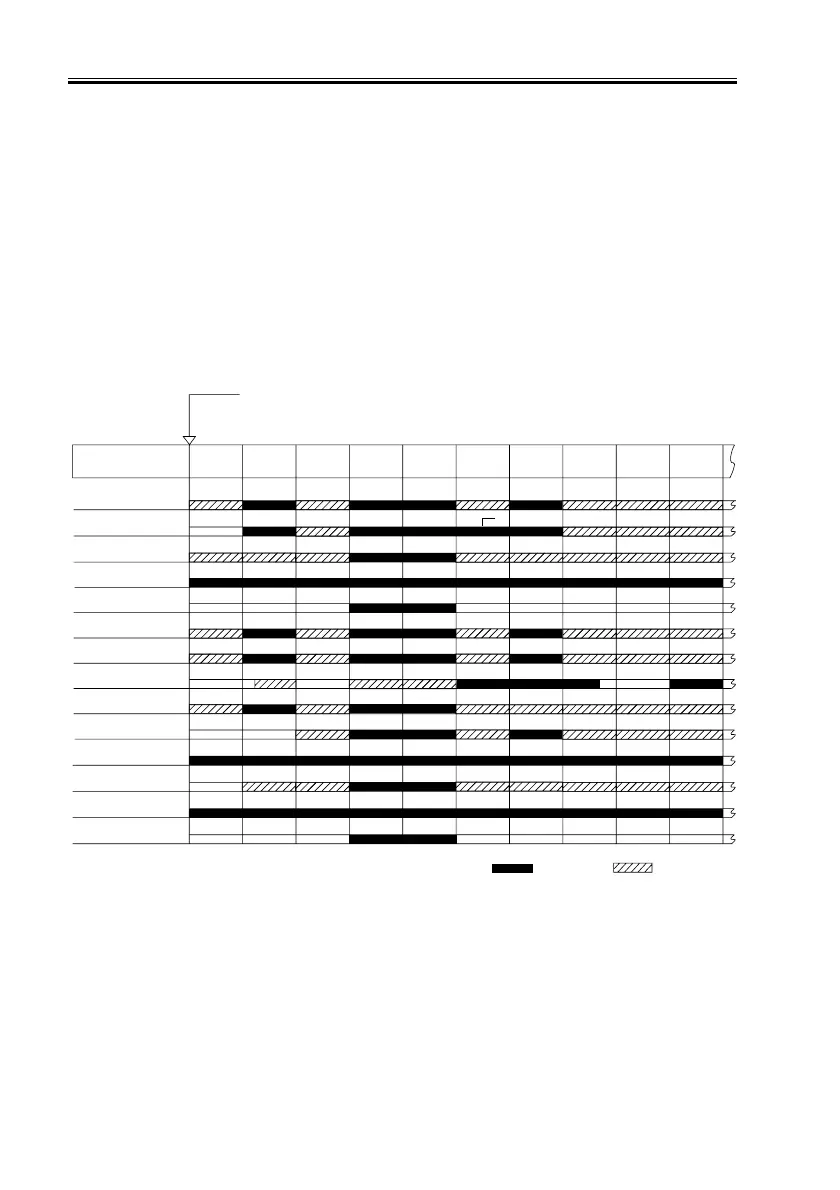
10.3 Sequence of Operations (fans)
Some fans of the machine operate in relation to the state of the printer unit, while some
operate in relation to the state of the scanning lamp; the sequence of each is shown in F02-
1003-01 and F02-1003-02.
The scanner cooling fan and the power supply cooling fan operate in relation to the states
of both the printer unit and the scanning lamp; however, the priority will be on the control
mechanism which has the higher speed.
In the event of an error or if the cover is opened, the state of fan operation immediately
before the incident will be maintained.
• Fans Operating in Relation to the State of the Printer Unit
F02-1003-01
Main power switch ON
State of printer unit
Initial
multiple
rotation
Standby Copying
After C,
standby
(others)
After C,
standby
(H/Hor29;
upper)
Printing
Primary charging
assembly fan (FM1)
Fixing heat discharge
fan (FM2)
Scanner cooling fan
(FM3)
Laser driver cooling fan
(FM5)
De-curling fan
(FM6)
Feeding fan
(FM7)
Drum fan
(FM8)
Pre-transfer charging
fan (FM10)
Power supply cooling
fan 1/2 (FM11,FM12)
Separation fan (FM13)
Laser scanner
cooling fan (FM14)
Developing fan
(FM15)
System fan (FM16)
Delivery adhesion-
proofing fan (FM17)
Warm-
up
After
copying
Pre-
heating
Jam
15 min.
: full speed : half speed
May be switched to full speed

 Loading...


