CHAPTER 2 NEW FUNCTIONS
2-153
COPYRIGHT
©
2001 CANON INC. 2000 2000 2000 2000 CANON iR8500/7200 REV.1 AUG. 2001
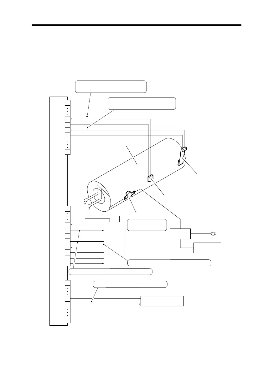
9.7 Error Detection
The following are checked in relation to the fixing temperature control mechanism:
[1] Temperature control error by the main thermistor (TH1)
[2] Sensor error by the sub thermistor (TH2)
[3] Overheating error by the thermal switch (TP1)
F02-907-01
DC controller PCB
J508B
1
7
8
10
20
S-TEMP
0V
0V
M-TEMP
Voltage according to the
reading of the main thermistor
Upper fixing roller
Main
heater
Sub thermistor
Main thermistor
Thermal switch
9
J505A
0V
0V
MHDTC
SHDTC
ZEROCROSS
100/200V detect
SH-ON
MH-ON
J512A
24V
Relay-OFF
Voltage according to the
reading of the sub thermistor
Turns off the AC
line at 228˚C.
RLY
Relay
Front cover
AC
driver
Relay PCB
Sub heater
When ‘0’, the AC relay is cut off.
17
17
16
1
12
11
15
1
11
13
14
10
10
When ‘1’, the main heater goes ON.
When the sub heater is powered, ‘0’.

 Loading...


