CHAPTER 2 NEW FUNCTIONS
2-27
COPYRIGHT
©
2001 CANON INC. 2000 2000 2000 2000 CANON iR8500/7200 REV.1 AUG. 2001
2.9.3 PCBs
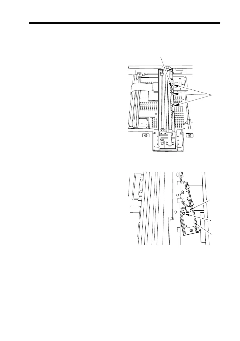
a. Removing the Light Adjustment PCB
1) Remove the copyboard glass.
2) Remove the screw [1] from the No. 1
mirror base assembly; then, while push-
ing down the claws [2], detach the light
adjustment PCB holder.
F02-209-24
3) Disconnect the connector J165 [1], and
remove the screw [2]; then, detach the
light adjustment PCB [3].
F02-209-25
[2]
[1]
[1]
[2]
[3]

 Loading...


