LASER UNIT 15 February 2006
3-30
3.5.4 LASER UNIT ALIGNMENT
WARNING
If you have just disassembled the LD unit, to avoid serious damage to the
eyes from accidental exposure to laser beams you must confirm that the
machine has been re-assembled completely before operation.
This adjustment corrects the parallelogram pattern to the desired rectangular
pattern for printing; it does not correct the skew of scanned images.
1. Execute SP2902-003 (Test Pattern – Printing Test Pattern) 018 to print the A4
LEF pattern. Check the printed patterns and estimate the angle of adjustment
required.
2. Remove the exposure glass (☛ 3.4.2).
3. Remove the LD unit cover and polygon motor cover (☛ 3.5.2).
4. Remove the right cover (☛ 3.3.3).
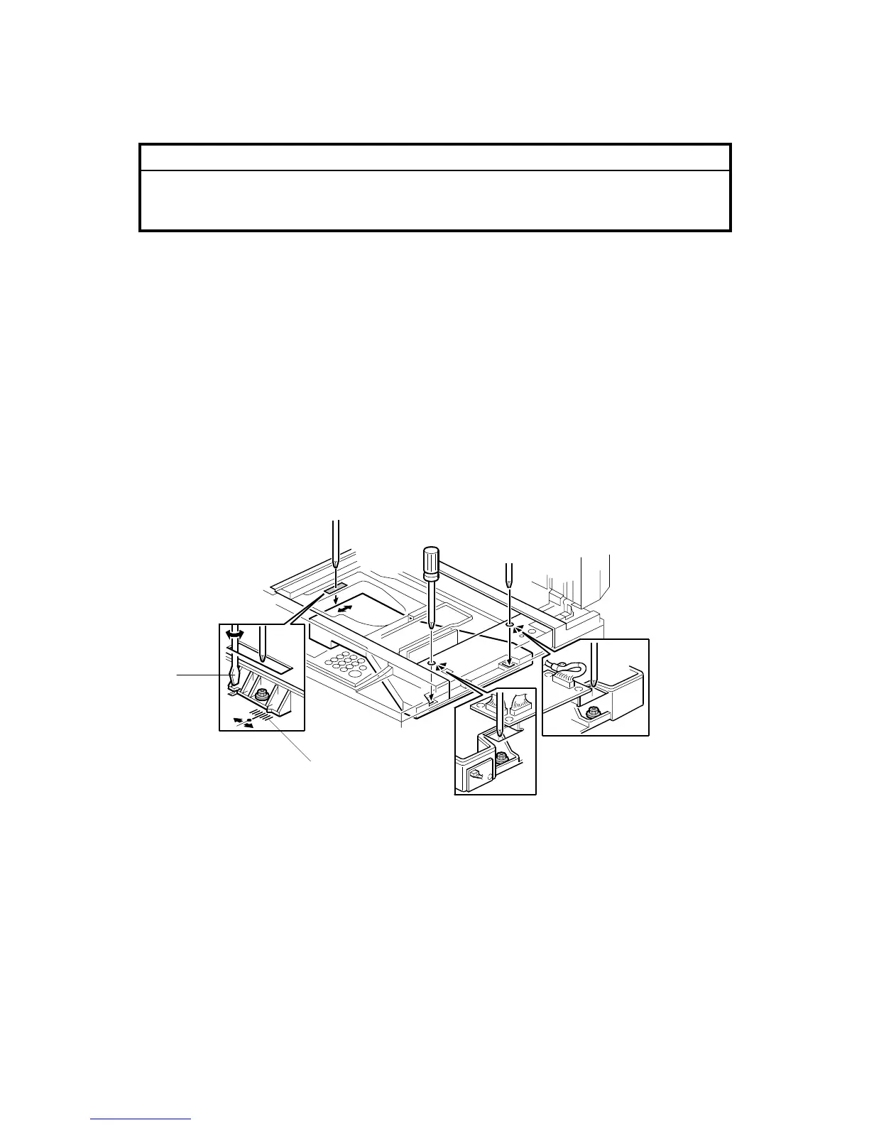
5. Loosen the screws of the laser exposure unit
( x 3).
6. While watching the scale [A], use a flathead screwdriver [B] to move the laser
exposure unit left or right to adjust the position of the unit.
B246R935.WMF
[A]
[B]
 Loading...