15 February 2006 DUPLEX UNIT
3-93
Replacement
Adjustment
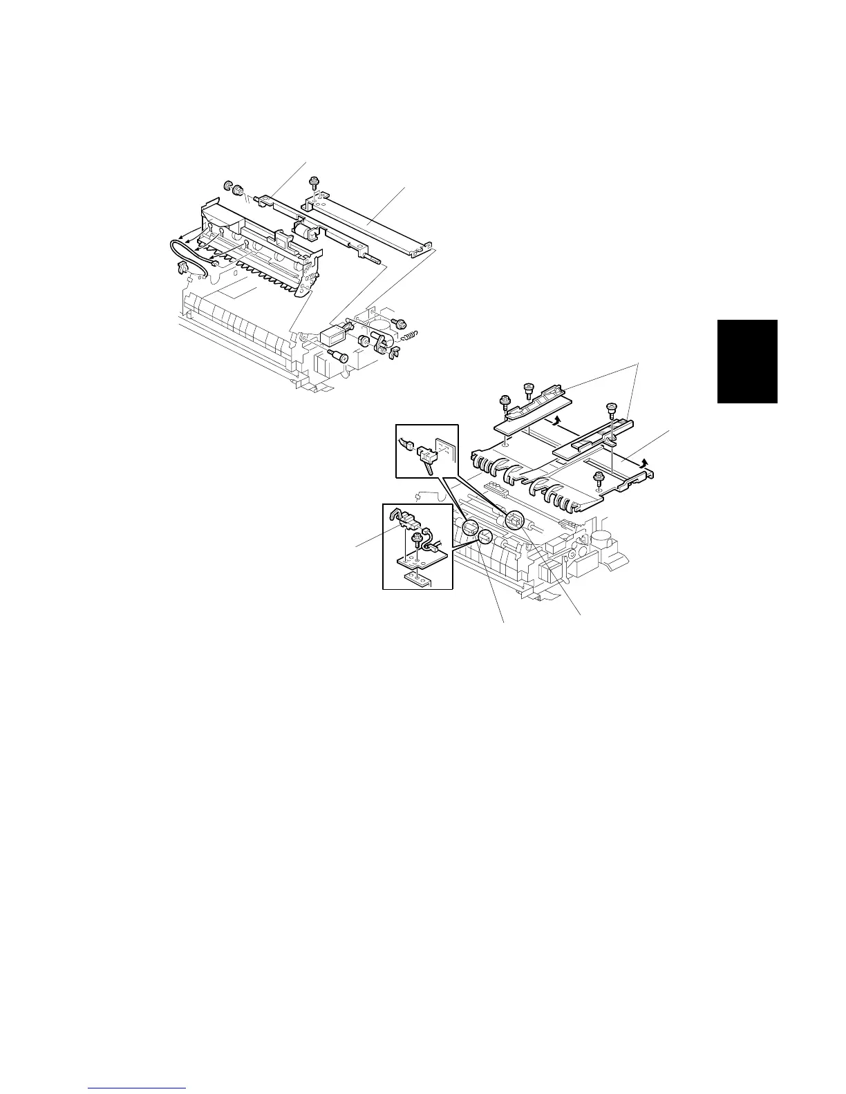
3.10.8 INVERTER EXIT SENSOR, TRANSPORT SENSORS 1 & 2
[A]: Cross-stay ( x 4)
[B]: Reverse trigger roller shaft
[C]: Jogger fences ( x 1 each)
[D]: Left half of table ( x 2)
• The front screw is a shoulder screw. Insert the screws in the correct holes
when re-attaching.
• To avoid breaking the tabs under the left edge of the table, pull the table to
the right to disengage the tabs and then remove.
[E]: Inverter exit sensor ( x 1, harness x 1, x 1)
[F]: Transport sensor 1 (harness x 1, x 1)
[G]: Transport sensor 2 (harness x 1, x 1)
B246R1046.WMF
B246R1047.WMF
[A]
[B]
[C]
[D]
[E]
[F]
[G]
 Loading...