Home
Ricoh
All in One Printer
MT-C1
Ricoh MT-C1 User Manual
5
of 1
of 1 rating
865 pages
Give review
Manual
Specs
To Next Page
To Next Page
To Previous Page
To Previous Page
Loading...
PAPER FEED
15 February 2006
3-98
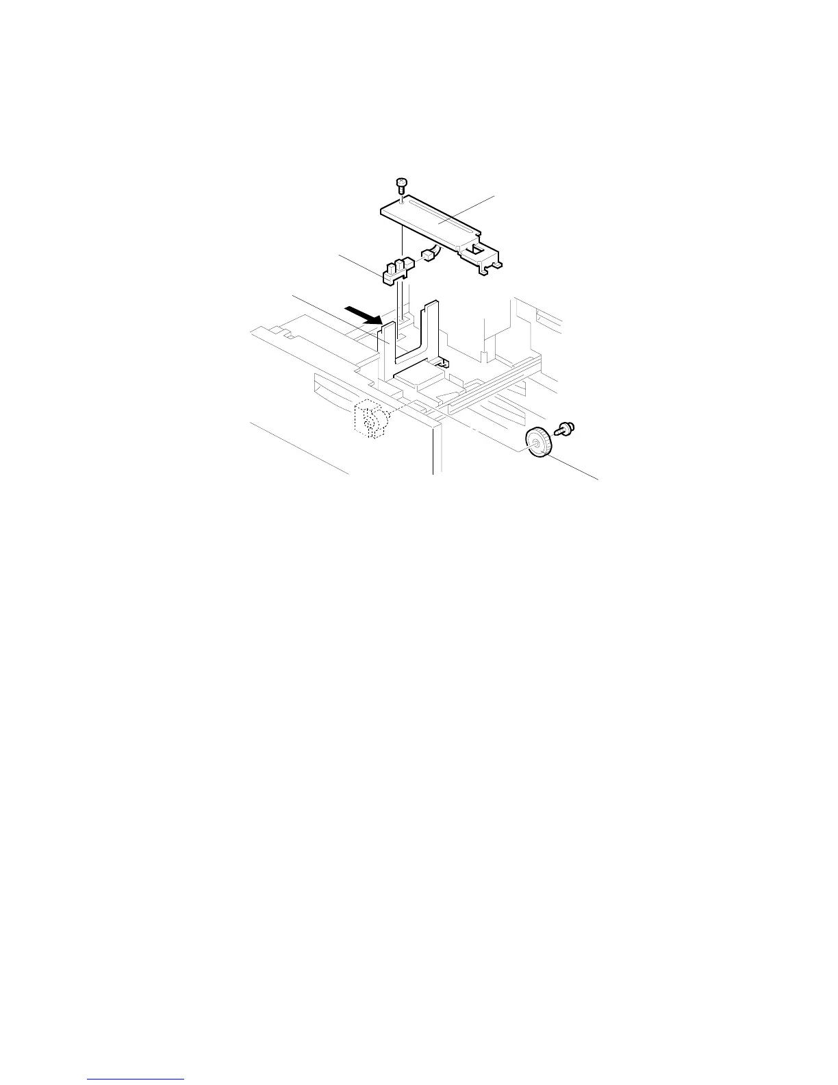
3.11.3
REA
R FENCE HP SENSOR REPLA
CEM
ENT
Turn off
the main switch.
Pull out the tandem feed tray
.
[A]:
Rear bottom plate (
x 1).
[B]:
Back fence transport gear (
x 1
)
[C]:
Move the back fence to the right.
[D]:
Rear HP sensor (
x 1)
B246R1055.WMF
[D]
[C]
[A]
[B]
326
328
Table of Contents
Default Chapter
1
Service Manual
1
Important Safety Notices
2
Laser Safety
3
Table of Contents
5
Installation
23
Installation Requirements
23
Operating Environment
23
Machine Level
24
Minimum Space Requirements
25
Dimensions
26
B064 Series
26
B140 Series
27
B246 Series
28
Peripheral/Option Summary Table
29
Power Requirements
32
Main Machine (B064 Series/B140 Series/B246 Series)
34
Installation Procedure
34
Removing Tapes and Retainers
34
Connecting the ADF
36
Removing and Filling the Development Unit
37
Re-Installing the Development Unit
39
Initializing the Drum Settings (B064 Series)
40
Initializing the Drum Settings (B140/B246 Series)
41
Tandem Tray
42
Date/Time Setting
44
Machine Level
44
SP Codes
44
A3/Dlt Feeder Kit (B475)
45
Accessory Check
45
Installation Procedure
46
Lct (B473)
48
Accessory Check
48
Installation Procedure
49
Removing Tape
49
Installing the LCT
50
Preparing the Main Machine
50
Lg/B4 Feeder Kit (B474)
52
Accessory Check
52
Installation Procedure
53
3000-Sheet Finishers (B468/B469/B674)
56
Accessory Check
56
Installation Procedure
57
Removing Tapes and Retainers
57
Installation
59
Enabling Booklet Binding
62
Selecting the Staple Supply Name
62
Punch Unit (B377)
63
Accessory Check
63
Installation Procedure
64
Cover Interposer Tray (B470)
66
Cover Interposer Tray (B470)
67
Installation Procedure
67
Removing Tapes and Retainers
67
Attaching the Extensions
68
Attaching the Interposer Tray
69
Attaching the Corner Plates for the B478/B706
70
Right Rear Corner Plate (B478/B706 Only)
70
Right Front Corner Plate (B478/B706 Only)
71
Attaching the Finisher to the Machine
72
9-Bin Mailbox (B471)
74
Accessory Check
74
Installation Procedure
75
Installation
75
Removing Tapes and Retainers
75
3000 Sheet Finisher (B478/B706)
77
Accessory Check
77
Installation
78
Moving the Finisher to a New Location
80
Punch Unit (B531/B812)
81
Accessory Check
81
Installation
82
Jogger Unit (B513)
86
Accessory Check
86
Installation Procedure
87
Z-Folding Unit (B660)
88
Z-Folding Unit (B660)
89
Installation Procedure
89
Before You Begin
89
Unpacking
90
Docking to the Finisher
91
Docking to the Main Frame
94
Z-Folding Unit (B660)
95
2000/3000 Sheet Finishers (B700/B701)
97
Installation Procedure
97
Removing Tapes and Retainers
97
Sheet Finisher B700
98
Docking the Finisher
100
Attaching the Trays
103
Leveling the Finisher
104
Enabling Booklet Binding (B700 Only)
105
Selecting the Staple Supply Name
105
Auxiliary Trays
106
Punch Unit (B702)
108
Accessories
108
Installation Procedure
109
Cover Interposer Tray (B704)
112
Cover Interposer Tray (B704)
113
Installation Procedure
113
Removing Tapes and Retainers
113
Preparing the Finisher (B700/B701/B706)
114
Attaching the Extensions for the B706
115
Prepare the Cover Interposer for the B706
116
Attach the Extensions to the B706
117
Attaching the Extensions for the B700/B701
118
Attaching the Interposer Tray (B700/B701/ B706)
119
Attaching the Corner Plates for the B706
120
Docking the Finisher and Interposer to the Machine (B700/B701/B706)
122
Output Jogger Unit (B703)
124
Accessories
124
Installation Procedure
125
Mail Box (B762)
127
Accessory Check
127
Installation Procedure
128
Copy Tray (B756)
131
Accessories
131
Installation
132
Key Card Bracket (B498), Key Counter Bracket (B452)
135
Key Card Bracket B498 Accessories
135
Key Counter Bracket B452 Accessories
136
Installation
137
Assemble the Key Counter Bracket
137
Install the Key Card Bracket and Assembled Key Counter
138
Copy Connector Kits
140
Copy Connector Kit (B525-10, -12) for B064 Series
140
Accessory Check
141
Installation
142
Installing the Hardware
143
Copy Connector Kit (B328-03) for B140 Series
147
Accessory Check
147
Preparation
148
Installation
149
Copy Connector (B842) for B246 Series
152
Accessories
152
Preparation
153
Installation
154
Mfp Options: B064 Series
157
Printer/Scanner Kit (G338), Printer Kit (G339)
157
Accessory Check
157
Installation Procedure
158
Inserting Dimms
158
Installation Procedure
159
Ps3 (B525-08)
161
Usb 2.0 (B525-01)
162
Accessory Check
162
Installation Procedure
162
USB SP Settings
163
Ieee1394 (G561) Firewire Interface
164
Accessory Check
164
Installation Procedure
165
UP Mode Settings for IEEE 1394
166
SP Mode Settings for IEEE 1394
167
Ieee802.11B Wireless Lan (G628)
168
Accessory Check
168
Installation Procedure
169
UP Mode Settings for Wireless LAN
170
Sp Mode Settings for 802.11B Wireless Lan
172
File Format Converter (Mlb) (B519)
173
Accessory Check
174
Installation Procedure
174
Installing the Firmware
174
Installing the Hardware
175
Mfp Options: B140 Series
176
Merging Applications on One Sd Card
176
Overview
176
Merging Applications
177
Undo Exec
178
Storing Copied SD Cards on Site
179
Overview
180
Printer/Scanner Kit (B659)
181
Accessory Check
181
Installation
182
Ps3 (B525-15)
185
Accessory Check
185
Installation
185
Usb 2.0 Interface Board (B596-01)
186
Accessory Check
186
Installation
186
Ieee 1394 Interface Board (B581-01)
187
Accessory Check
188
Installation
188
Ieee 802.11B Interface Board (B582-01, -02)
188
Accessory Check
190
Installation
190
Bluetooth Interface Unit (G377)
190
Accessory Check
191
Installation
191
File Format Converter (B609)
191
Accessory Check
192
Data Overwrite Security Unit (B735)
192
Seal Check and Removal
193
Installation Procedure
194
Mfp Options: B246 Series
197
Overview
197
Common Procedures
198
Inserting SD Cards
198
Storing Copied SD Cards
198
Printer Scanner Kit (B841)
199
Installation
200
Postscript3 (B525)
203
Accessories
203
Installation
203
Accessories
204
Ieee1394 Interface Board (B581)
204
Wireless Lan G813 (802.11B)
205
Accessories
205
Installation
205
Bluetooth Interface Unit Type C B826
206
Accessories
206
Installation
206
File Format Converter Type C B609
207
Accessory Check
208
Data Overwrite Security Unit Type C B735
208
Seal Check and Removal
209
Installation Procedure
210
Remote Communication Gate Type Cm1 (B818)
213
Accessories
213
Installation
213
Usb Host Interface Unit Type a (B825)
216
Accessory Check
216
Installation
216
Browser Unit Type B (B828)
217
Accessories
217
Installation
217
Copy Data Security Unit Type C (B829)
218
Accessories
218
Installation
218
Accessories
220
Installation
220
VM Card (B861)
220
Ieee1284 B679
221
Accessories
221
Installation
221
Gigabit Ethernet G381
222
Accessories
222
Installation
222
Preventive Maintenance
223
Pm Tables
227
Adf
227
Optional Peripheral Devices
227
Cover Interposer Tray B470
227
LCT (Large Capacity Tray) B473
227
3000-Sheet Finisher with 50-Sheet Stapler and Saddle-Stitching
228
B468/B469/B674
228
Z-Folding Unit Type 2105 (B660)
228
Punch B702
229
Related Sp Codes
229
Sheet Booklet Finisher B700/B701
229
Replacement and Adjustment
230
General Cautions
230
Drum
230
Drum Unit
230
Transfer Belt Unit
231
Scanner Unit
231
Laser Unit
231
Charge Corona
232
Development
232
Cleaning
233
Fusing Unit
233
Paper Feed
233
Used Toner
233
Special Tools and Lubricants
234
Special Tools
234
Lubricants
234
Operation Panel and External Covers
235
Operation Panel
235
Front Door
235
Right Covers
236
Left Covers
237
Rear Covers
238
Scanner
239
Adf and Top Covers
239
Adf
239
Top Covers
240
Exposure Glass
242
Scanner Original Size Sensors
242
Lens Block
243
Exposure Lamp
244
Lamp Regulator
245
Scanner Motor Drive Board (Sdrb)
246
Scanner Motor
247
Scanner Hp Sensor
248
Scanner Wire Replacement
249
Preparation for Removal
249
Wire Removal: Back
250
Wire Removal: Front
251
Attaching the New Wire
252
Scanner Heater
254
Laser Unit
255
Caution Decals
255
Ld Unit and Polygon Motor
256
Laser Synchronization Detector Replacement
258
Laser Unit Alignment
259
Drum Unit
261
Development Unit Removal
261
Removal
261
Re-Installation
262
Replacement with a Used Development Unit
262
Charge Corona Unit
263
Charge Corona Wire and Grid
264
Charge Corona Wire Cleaning Pads
265
Opc Drum Removal
266
Dusting the Drum Surface
267
Ptl (B140 Series Only)
268
Quenching Lamp
269
Drum Potential Sensor
269
Cleaning Filter
270
Cleaning Blade
270
Cleaning Brush
271
Pick-Off Pawls
272
ID Sensor
272
Drum Motor
273
Toner Collection Bottle
274
Toner Separation Unit
274
Ozone Filters
275
Optics Dust Filter
275
Internal Dust Filter
275
Development Unit
276
Developer Replacement
276
Development Filter
278
Entrance Seal and Side Seals
279
Td Sensor
280
Toner End Sensor
280
Toner Supply Motor
281
Development Motor
282
Transfer Belt Unit
283
Transfer Belt
284
Transfer Roller Cleaning Blade
286
Discharge Plate
287
Transfer Power Pack
288
Fusing Unit
289
Fusing Pressure Release Motor (B140 Series)
291
Fusing Pressure Release Hp Sensor (B140 Series)
292
Fusing Unit Thermistors and Thermostats
293
B064 Series
294
B140 Series
294
B246 Series
294
Web Cleaning Roller
296
Web Unit Disassembly
296
Web Unit Assembly
297
Web Motor and Web End Sensor
298
Pressure Roller Cleaning Unit
299
B064 Series
299
B140 Series
300
Fusing Lamps, Hot Roller, and Pressure Roller
301
B064 Series: Fusing Lamps
301
B140 Series: Fusing Lamps
302
Important Notes about Fusing Unit Assembly (B064 Series)
307
Pressure Roller
308
Stripper Pawls
309
B064 Series
309
B140 Series
310
Stripper Pawls
310
Nip Band Width Adjustment
311
Fusing Unit Exit Sensor
312
Fusing/Exit Motor
313
Fusing Exit and Exit Unit Entrance Sensors
314
Duplex Unit
315
Duplex Unit Removal
315
Duplex Unit Side-To-Side Adjustment
316
Jogger Fence Adjustment
316
Duplex Motors
317
Duplex Inverter Motor
317
Duplex Jogger and Transport Motors
318
Duplex Transport Clutch/Jogger Hp Sensor
319
Duplex Entrance Sensor
320
Duplex Transport Sensor 3
321
Inverter Exit Sensor, Transport Sensors 1 & 2
322
Duplex Jogger Belt Adjustment
323
Paper Feed
324
Paper Tray Removal
324
Paper Feed
325
Rear Fence Return Sensor Replacement
326
Rear Fence Hp Sensor Replacement
327
Tandem Right Tray Paper Sensor Replacement
328
Bottom Plate Lift Wire Replacement
329
Tandem Tray Paper Size Change
331
Pick-Up, Feed, Separation Roller Replacement
334
Feed Unit
335
Feed Unit
336
Separation Roller Pressure Adjustment
337
Relay Sensor
338
By-Pass Paper Size Detection Board
339
By-Pass Tray Rollers
340
By-Pass Separation Roller Pressure Adjustment
341
Registration Sensor
342
Registration and By-Pass Unit Removal
343
Pcbs and Hdd
345
Bcu Board (Base Engine Control Unit)
345
BCU: B064, B140 Series
345
BCU, IOB: B246 Series
346
Controller Board
347
B064 Series: Controller Board
347
B140 Series: Controller Board
348
B246 Series: Controller Board
349
Ipu Board
350
B064 Series: IPU Board
350
B140 Series: IPU, Mother Board
351
B246 Series: IPU
354
B246 Series Motherboard
355
Development Power Pack
357
Psu, Pfc Boards
358
B064 Series
358
B140 Series PSU
358
B246 Series PSU
359
Hdd
360
B064 Series HDD
360
B140 Series HDD
361
B246 Series HDD
362
Nvram
363
NVRAM: B064 Series, B140 Series
363
NVRAM: B246 Series
365
Dimms
367
Adf
368
Adf Covers
368
Feed Unit
369
Feed Belt and Pick-Up Roller
370
Feed Unit
370
Separation Roller
371
Registration Sensor
372
Adf Control Board
373
Original Width, Interval, and Skew Correction Sensors
374
Original Length Sensors
375
Df Position and Aps Sensor
376
Other Adf Sensors
377
Bottom Plate Lift Motor
378
Feed Motor
378
Exit Motor and Transport Motor
379
Bottom Plate Lift Motor
379
Pick-Up Roller Motor and Hp Sensor
380
Cis Power Supply Board and Cis Unit
381
Adf Exit Sensor
382
Copy Image Adjustments: Printing/Scanning
383
Printing
383
Registration - Leading Edge/Side-To-Side
383
Blank Margin
384
Registration Buckle Adjustment
384
Scanning
385
Magnification
385
Adf Scanning Adjustments
386
ADF Skew Correction
386
DIP Switch Settings (ADF Main Board)
386
Vertical Black Lines
386
Scanning
386
Touch Screen Calibration
388
Troubleshooting
389
Overview
389
Recovery Methods
390
Important Sp Codes
390
Download Error Codes
391
Jam Detection
394
Sensor Locations
394
Timing Charts
395
Feed Motor
395
Feed, Transport, Feed Out: Face-Up
395
Transport, Inverter, Feed Out: Face-Down
396
Duplex Transport
397
Program Download
398
B064 Series Service Mode
399
B064 Series Service Call Conditions
399
B064 Series Sc Code Descriptions
400
SC100: Scanning System
400
SC300: Image Development System (1)
403
SC400: Image Development System (2)
408
SC500: Feed, Transport, Duplexing, and Fusing Systems
409
SC600: Data Communication
412
SC700: Peripherals
414
SC800: Overall System
417
SC900: Miscellaneous
420
Additional Sc Codes Printed in Smc Report
422
B140/B246 Series Service Mode
425
Service Mode Lock/Unlock
425
B140/B246 Series Service Call Conditions
426
B140/B246 Series Sc Code Descriptions
427
SC100: Scanning System
428
SC200: Exposure
431
SC300: Image Development System (1)
432
SC400: Image Development System (2)
437
SC500: Feed, Transport, Duplexing, and Fusing Systems
438
SC600: Data Communication
443
SC700: Peripherals
445
SC800: Overall System
454
SC900: Miscellaneous
460
Main Unit: Paper Jam Errors
464
Jam Codes
464
Finisher B468/B674 Jam Codes
465
Finisher B469 Jam Codes
465
Cover Interposer Tray B470 Jam Codes
466
Finisher B478/B706 Jam Codes
466
Mailbox B471 Jam Codes
466
Z-Folding Unit B660 Jam Codes
467
Additional Sc Codes Printed in Smc Report
468
Other Problems (B064/B140/B246 Series)
471
Blown Fuse Conditions
471
Common Problems
471
Frequent Paper Jams
472
Service Tables
474
Service Program Mode
474
Service Program Mode Operation
474
Service Mode Lock/Unlock
474
To Enter and Exit the Service Mode
475
To Enter and Exit the Super SP Mode
475
To Switch to the Copy Window for Test Printing
475
Using the SP Mode
476
SP Mode Button Summary
477
SP Mode Print (SMC Print)
478
Resets
479
Memory All Clear: Sp5801
479
Software and Setting Reset
483
Resetting Copy/Document Server Features Only
483
Resetting Scanner Features Only
483
Resetting the System
483
Software Reset
483
Test Pattern Printing
484
Printing Test Pattern: Sp2902-003
484
Test Pattern Table
485
Ipu Front/Back Test Patterns: Sp2902-001,002
486
Test Pattern Table
487
Ipu Printing Test Pattern: Sp2902-004
488
Software Update
489
Software Update Procedure: B140/B246 Series
489
Error Message Table
493
Downloading Stamp Data
494
Updating the LCDC for the Operation Panel
494
NVRAM Data Upload/Download
495
Software Update Procedure: B064 Series
496
GW Controller/Bcu Update
497
Forced Update
498
Stamp Data Update
498
Operation Panel Software Update
499
Netfile Firmware Update
500
NIB Update
500
Scanner Update
500
Firmware Update Notes
501
NVRAM Update
501
Service Program Mode Tables
502
Service Table Key
502
Copier Service Table
503
Sp1Xxx Feed
503
Sp2Xxx Drum
508
Sp3Xxx Processing
526
Sp4Xxx Scanner
529
Sp5Xxx Mode
540
Sp6Xxx Peripherals
592
Sp7Xxx Data Logs
603
Sp8Xxx: Data Log2
620
Printer Service Table
649
Scanner Service Table
650
Input/Output Check
662
Copier Output Check: Sp5804
668
Adf Input Check: Sp6007
670
Adf Output Check: Sp6008
671
Finisher Input Check: Sp6117 (B478/B704)
672
Finisher Output Check: Sp6118
674
Finisher 1 Input Check: 6121
675
Finisher 1 Output Check: 6124
676
Finisher 2 Input Check: 6122
677
Finisher 2 Output Check: 6125
678
Using the Debug Log (B140/B246)
679
Retrieving the Debug Log from the Hdd
682
Recording Errors Manually
683
New Debug Log Codes
684
User Tools
685
System Settings
686
B140 Series System Settings
688
Copier/Document Server Features
691
Inquiry
695
Dip Switch Tables
696
Detailed Descriptions
697
Paper Path (with Cover Interposer Tray)
699
Paper Path (with 9-Bin Mailbox)
700
Drive Layout
701
Board Structure
702
Component Descriptions
703
SBU (Sensor Board Unit)
704
HDD (Hard Disk Drive)
705
Copy Process Overview
706
Overview
708
Adf Drive Layout
709
Pick-Up Roller Lift
710
Bottom Plate Lift
711
Original Separation
712
Original Transport
713
Original Skew Correction
714
Original Size Detection
716
Adf Scanning
719
Jam Detection
720
Scanning
721
Scanner Drive
722
Original Size Detection
723
Detection Timing
724
Scanning Magnification
725
Auto Image Density (Ads)
726
Image Processing
727
Image Processing Flow
728
Image Processing Modes
729
Image Quality Sp Adjustments
730
Custom Settings for each Mode: Line Width Correction
732
Custom Setting: Duplex Scanning Mode Original Image Quality Settings
734
Settings Adjustable for each Original Mode
735
Relation between the Sp and up Settings
736
Image Processing Troubleshooting
738
Removing Vertical White Lines During Duplex Scanning
739
Equalizing Duplex Scanned Image Quality of Front/Back Sides
740
Laser Exposure
741
Optical Path
742
Four-Beam Exposure
743
Cooling Fan
744
Ld Safety Switches
745
B246 Series Safety Switches
746
Drum Unit
747
Opc Drum
748
Drum Charge
749
Charge Corona Wire Cleaning
750
Drum Pick-Off Mechanism
751
Drum Cleaning
752
Drum Ventilation and Ozone Filter
753
Toner Recycling
754
Waste Toner Collection
755
Process Control
756
Drum Potential Sensor Calibration
757
Development Bias, Bias Grid, and LD Adjustment
758
ID Sensor Calibration (Vsg)
760
Development and Toner Supply
761
Toner Supply
762
Development Unit
763
Developer/Toner Mixing (Agitation)
764
Development Bias
765
Toner Supply
766
Development Unit Drive and Ventilation
767
Toner End Sensor
768
Toner Bottle Supply and Ventilation
769
Toner Supply Control
770
Pixel Count Toner Supply Mode
771
TD Sensor Initialization
772
Toner Supply Without ID Sensor and TD Sensors
773
Toner End Detection
774
Image Transfer and Paper Separation
775
Transfer Belt Lift
776
Timing
777
Transfer Belt Charge
778
Transfer Current Settings
779
Transfer Current Circuit
780
Transfer Belt Drive and Paper Transport
781
Transfer Belt Cleaning
782
Anti-Condensation Heater
783
Paper Feed
784
Tray Capacities
785
Drive
786
Tray and Paper Lift Mechanism – Tray 2,3
787
Lift Sensor
788
Paper Feed and Separation Mechanism
789
Paper Feed and Separation
790
Separation Roller Release Mechanism
791
Paper Near-End and Paper End – Trays 2 and 3
792
Paper Size Detection
793
Anti-Condensation Heaters
794
Tandem Tray – Tray 1
795
Connecting the Left and Right Sides of the Tray
796
Paper Lift/Remaining Paper Detection
797
Fence Drive
799
Rear Fence Drive
800
Tray Side-To-Side Positioning
801
Tray Positioning Mechanism – Trays 1 to 3
802
By-Pass Tray
803
By-Pass Tray Paper End Detection
804
By-Pass Paper Size Detection
805
Paper Registration
806
Paper Registration Drive
807
Jam Removal at Paper Registration
808
Image Fusing and Paper Exit
809
B140 Series
810
Fusing Mechanism
811
B140 Series
812
Pressure Roller
813
B140 Series
814
Hot Roller Cleaning
815
Web Drive
816
Fusing Unit Entrance Guide
817
Fusing Unit Drive
818
Cpm down Mode
819
Fusing Temperature Control
820
Exit
822
Exit Junction Gate
823
Duplex Unit
824
Duplex Drive
825
Inverter Operation
826
Inverter Feed-Out
827
Duplex Tray Feed
828
Duplex Interleave Feed
829
Energy Saver Modes
831
Return to Stand-By Mode
832
Return to Stand-By Mode
833
Auto off Mode
834
Night Mode
835
Copier
836
Power Consumption
838
Specifications
836
Machine Configuration
840
A3/Dlt Kit (B475)
841
Sheet Finisher with Saddle-Stitch and 50-Sheet Stapler (B468)
842
Staple Specifications
843
Sheet Finisher with 50-Sheet Stapler (B469)
844
Sheet Finisher with Saddle-Stitch and 50-Sheet Stapler (B674)
845
Lower Tray
846
Staple Specifications
847
Punch Unit (B377)
848
Cover Interposer Tray (B470)
849
Sheet Finisher (B478/B706)
850
Punch Unit (B531)
851
Punch Unit (A812)
852
Jogger Unit (B513)
853
Jam History
863
5
Based on 1 rating
Ask a question
Give review
Questions and Answers:
Need help?
Do you have a question about the Ricoh MT-C1 and is the answer not in the manual?
Ask a question
Ricoh MT-C1 Specifications
General
Brand
Ricoh
Model
MT-C1
Category
All in One Printer
Language
English
Related product manuals
Ricoh M0A0
776 pages
Ricoh M052
667 pages
Ricoh M 320
24 pages
Ricoh MET-C1
688 pages
Ricoh M 2701
2 pages
Ricoh MP 161
192 pages
Ricoh M C2000
24 pages
Ricoh mp c300
28 pages
Ricoh MP 2352
8 pages
Ricoh MP 2001
156 pages
Ricoh MP 6503
228 pages
Ricoh MP C401
10 pages
 Loading...