C4 User Manual
October 25, 2021 ©2021 Smartrise Engineering, Inc. All Rights Reserved Page 127
2. Loosely attach the hardware to the Lower Tape Mount Assembly.
Figure 174: Hardware to Lower Tape Mount Assembly
3. Position the Lower Tape Mount Assembly 7.6” from the surface of the guide rail to the
center of the 3/8” bolt. See Figure 173.
4. Tighten the first hex nut to secure the Lower Tape Mount Assembly in place.
5. Thread the Nylock nut onto the bolt until the two flat washers located on each side of
the spring are just touching the spring loop. This nut does not need to be tightened.
6. Connect the spring to the tape interlock bracket using the split ring. See Figure 173.
7. Adjust the spring tension by raising or lowering the Unistrut mounting point so that the
spring is stretched to approximately 3”.
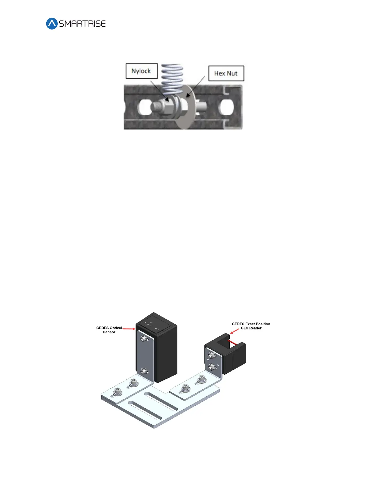
10.6 Sensor Array Assembly
The Sensor Array Assembly contains the CEDES Optical Sensor, CEDES Exact Position GLS
Reader, mounting brackets, and associated hardware. The sensors can be oriented differently
as long as the corresponding tape and blades are aligned correctly.
After assembly is complete, connect the CEDES Optical Sensor and the CEDES Exact Position GLS
Reader to the CT board and secure cabling.
Figure 175: Sensor Array Assembly