C4 User Manual
Page 24 ©2021 Smartrise Engineering, Inc. All Rights Reserved October 25, 2021
The Master/Slave switch is used to enable the secondary CAN network on the SR3031 board.
When the switch is in the slave position, CAN1 and CAN2 terminals are identical and service the
same network. When the switch is in the master position, CAN1 and CAN2 terminals are
different and service different networks.
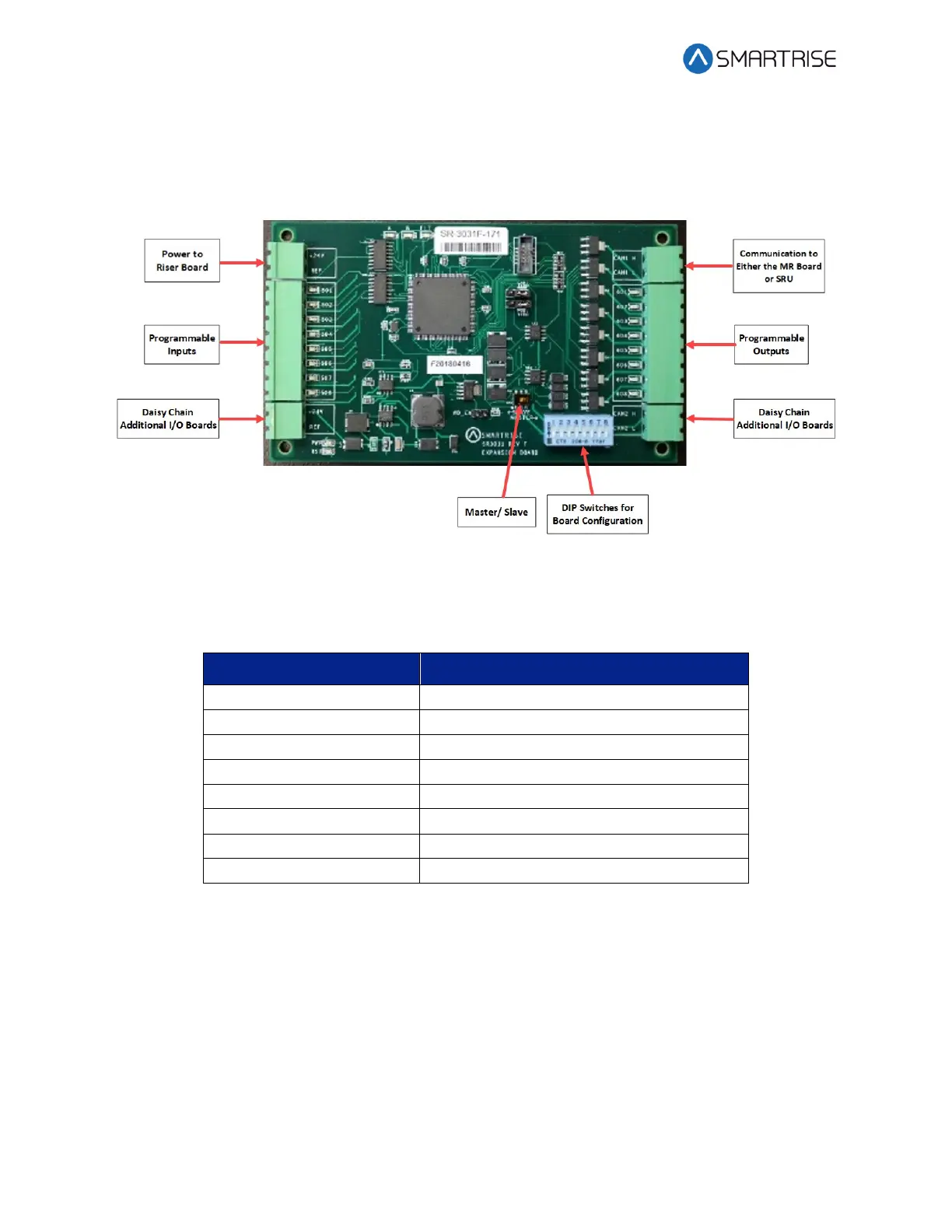
Figure 25: I/O Board/Riser Board SR3031
The table below lists the I/O Board SR3031 DIP switch settings.
Table 6: I/O Board SR3031 DIP Switch Settings
2.3.1 Group Redundancy
The Group Redundancy monitors pre-communicating Riser board(s). Group Redundancy is
dependent upon the number of Riser boards connected within the group. For example, if only
one Riser board is connected, then only one Riser board is monitored for loss of
communication. If four Riser boards are connected, then all four Riser boards are monitored for
loss of communication.
If any communicating Riser boards loses communication for more than 10 seconds, a signal is
sent to trigger a set of relays to shut down the primary set of Riser boards and start the
redundant set.