C4 User Manual
Page 132 ©2021 Smartrise Engineering, Inc. All Rights Reserved October 25, 2021
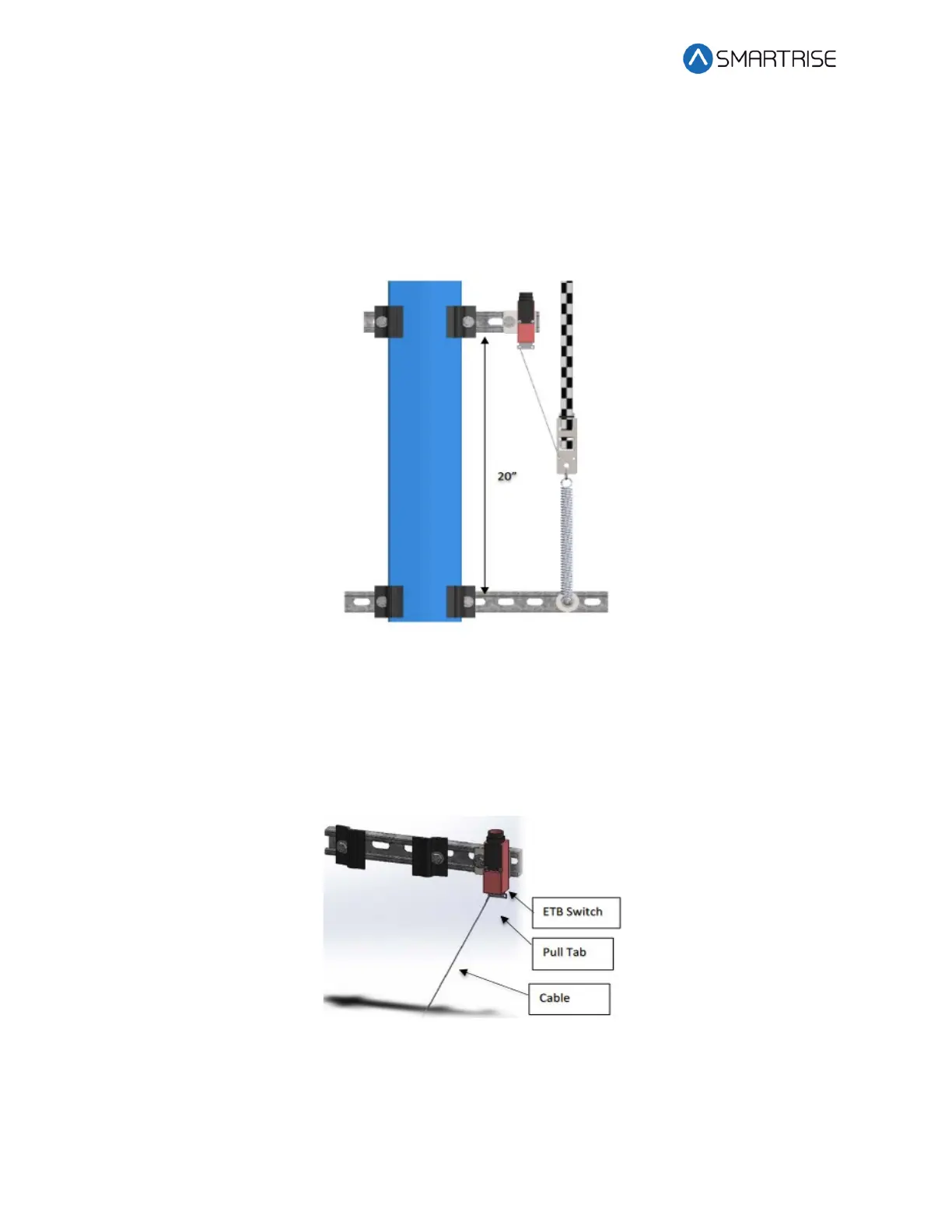
cable attachment out of the ETB switch, opening the safety string. Verify that the cable length
allows the tab to pull out of the ETB switch when the spring is retracted. See Figure 183.
The following procedure describes how to install the ETB Switch Assembly.
1. Affix a 12” length of Unistrut to the bottom of the guide rail approximately 20” above
the Lower Tape Mount Assembly Unistrut.
Figure 182: Unistrut to Lower Tape Mount Assembly
2. Attach bracket and ETB switch to the Unistrut.
3. Link the ETB switch to the tape interlock via the cable kit provided. Leave 1-2“ for slack
in the cable.
NOTE: The switch can be mounted vertically as well as by inserting a switch pull tab into
the bottom end, pull should always face downward.
Figure 183: Emergency Tape Break Switch