C4 User Manual
Page 26 ©2021 Smartrise Engineering, Inc. All Rights Reserved October 25, 2021
The assigned input for wiring is as follows:
• Inputs 501-508 – First address
• Inputs 509-516 – Second address
• Inputs 517-524 – Last address
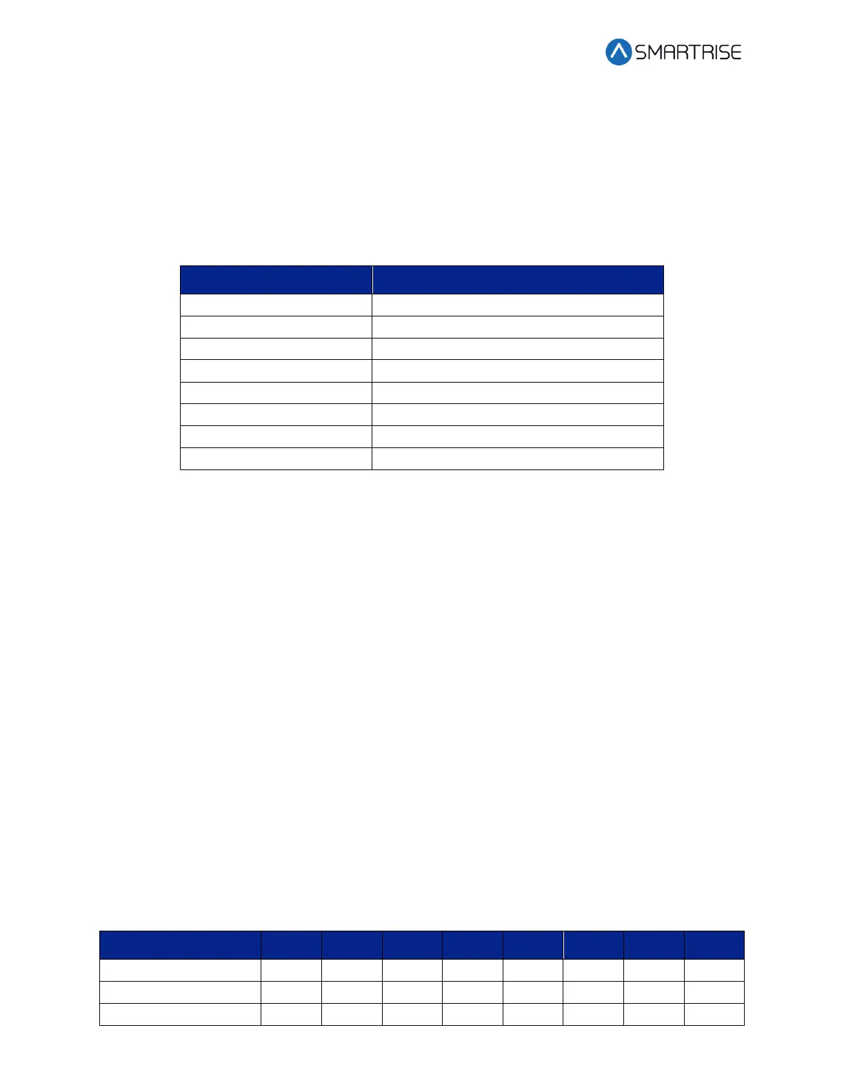
The table below lists the 24 Input Board SR3041 DIP switch settings.
Table 7: 24 Input Board SR3041 DIP Switch Settings
NOTE: This board will occupy the expansion board address shown on its DIPs, as well as the
next two slave addresses.
Depending upon the position of where the 24 Input board is within the controller, the DIP
switches have to be set to certain positions.
The address of the board depends on the type of board previously used. If the previous board is
a SR3041, the address is the previous board’s address +3. If the previous board is a SR3031, the
address is the previous board’s address +1.
If this Input board is the first board within the chain, turn OFF all DIP switches. The 24 Input
board will mimic SR3031 Expansion boards (1-3).
If this Input board follows directly after the first 24 Input board in the chain, turn ON DIP
switches 1 and 2 only. The 24 Input board will mimic SR3031 Expansion boards (4-6).
If another 24 Input board follows directly after the first two 24 Input boards within the chain,
turn ON DIP switches 2 and 3 only. The 24 Input board will mimic SR3031 Expansion boards (7-
9).
The table below lists the DIP switch settings for the 24 Input board when SR3041 is the master.
Table 8: 24 Input Board SR3041 DIP Switch Settings When SR3041 is Master