C4 User Manual
Page 22 ©2021 Smartrise Engineering, Inc. All Rights Reserved October 25, 2021
WARNING
DO NOT APPLY 24 VDC DIRECTLY TO THE OUPUT TERMINAL WITHOUT A CURRENT LIMITING
DEVICE. THIS WILL CAUSE DAMAGE TO THE OUTPUT TRANSISTORS.
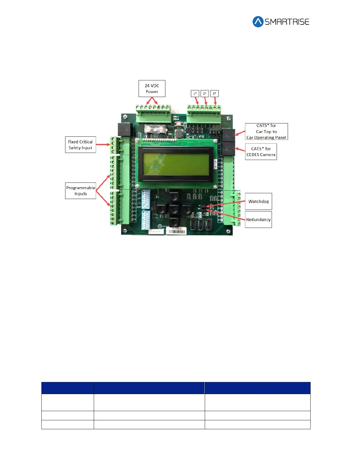
Figure 24: SRU Board SR3030
The serial communication is as follows:
• 1* (CN2+ CN2-) – Serial communication from the CT to the MR board for safety network.
• 2* (CN1+ CN1-) – Serial communication for devices on the car network.
• 3* (C3H and C3L) – Serial communication to third-party devices, for example, the Fixture
Driver board.
CAT5* – The CAT5 supplies power and two serial communication channels.
There are two sets of DIP switch settings for the SR3030 board. Bank A (upper) and Bank B
(lower). Each setting is configured for a different functionality.
The table below lists the functionality and configuration for the SRU board SR3030 Bank A DIP
switch settings.
Table 4: SRU Board SR3030 Bank A DIP Switch Setting Configuration