C4 User Manual
Page 18 ©2021 Smartrise Engineering, Inc. All Rights Reserved October 25, 2021
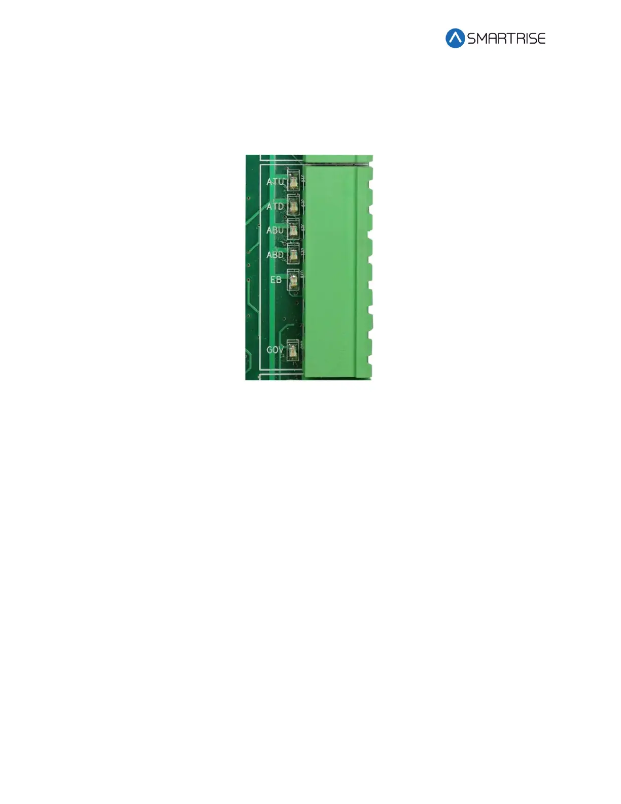
The following is an output terminal.
EB Terminal – Voltage output to either the rope gripper or the secondary brake contactor. In
case of the rope gripper, this terminal is connected to the primary or hot side of the rope
gripper. If a secondary sheave brake is being used, this is factory wired to the B2 contactor.
Figure 20: 120 VAC Input and Output Connector
2.1.11 Hall Lock Connections
WARNING
ALL CONNECTIONS ON THIS TERMINAL BLOCK ARE HIGH VOLTAGE. DISCONNECT POWER TO
THE CONTROLLER BEFORE WIRING THESE TERMINALS.
LRT Terminal – Terminates the rear top lock. The primary side of the lock is connected to L120
and the secondary side is wired back to this terminal.
LRM Terminal – Terminates the rear middle locks. The primary side of the lock is connected to
L120 and the secondary side is wired back to this terminal.
LRB Terminal – Terminates the rear bottom lock. The primary side of the lock is connected to
L120 and the secondary side is wired back to this terminal.
LFT Terminal – Terminates the front top lock. The primary side of the lock is connected to L120
and the secondary side is wired back to this terminal.
LFM Terminal – Terminates the front middle locks. The primary side of the lock is connected to
L120 and the secondary side is wired back to this terminal.
LFB Terminal – Terminates the front bottom lock. The primary side of the lock is connected to
L120 and the secondary side is wired back to this terminal.