C4 User Manual
October 25, 2021 ©2021 Smartrise Engineering, Inc. All Rights Reserved Page 135
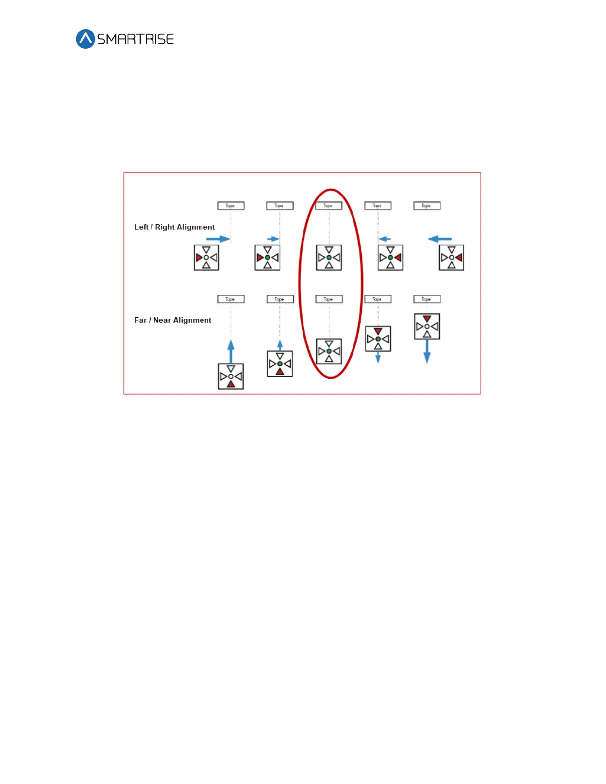
When the optical sensor needs to be aligned, the red arrow LEDs indicate which way to move
the sensor.
The following procedure describes how to align the optical sensor.
1. Loosen the two mounting bolts on sensor base plate or sensor bracket to adjust the
sensor position, as required.
Figure 187: Alignment Arrows
2. Position the sensor according to the LEDs.
• Left / Right Alignment – Using the direction arrows on top of the sensor, move the
camera left or right until only the green POS STAT LED is on.
• Far / Near Alignment – Using the directional arrows on top of the sensor, move the
sensor closer to or further away from the tape until only the green POS STAT LED in
on.
3. Once the sensor is aligned, tighten the two mounting bolts to the sensor base plate or
sensor bracket as applicable.
4. Run the car on INSPECTION from terminal to terminal while watching the POS LED on
top of the sensor.
5. Is the sensor aligned with the tape for the entire length of travel?
a. If the sensor is aligned, the process ends.
b. If the sensor is not aligned, go to step 1.
NOTE: As the car runs up and down the hoistway, the red alignment arrow LEDs may
flash on and off. This is OK if the center green LED stays on.