C4 User Manual
October 25, 2021 ©2021 Smartrise Engineering, Inc. All Rights Reserved Page 213
19 Serial Hall Lanterns
Serial Hall Lantern Hall boards, which are interchangeable with Hall Call boards, connect to the
CAN network of the MR board. Since the Serial Hall Lantern Hall boards and the Hall Call boards
share the same hardware and software, this manual references Hall boards.
19.1 CAN BUS
The Serial Hall Lantern Hall board CAN bus follows the same CAN bus guidelines as the Hall
boards.
By default, the CAN network is terminated on the MR board so only terminate the lowest
landings Serial Hall Lantern Hall board. If a CE Driver board is being used within the network,
the termination on this board is removed.
19.2 Hall Lantern Masks
To enable hall lantern communications, the car’s hall lantern mask must be set. The setting is
located under address 08-0213. The value for the address varies depending on the function IDs
of the Serial Hall Lantern Hall boards installed. To determine the value of the address, use Table
32 or Table 33 and add the corresponding values of each of the Function IDs serviced by the
car. See section 5 Parameters to set the decimal format for Hall Lantern Masks.
To configure the Serial Hall Lantern Hall Call boards to serve as rear calls, set the rear hall
lantern mask located under address 32-0036 to the corresponding value. Use the values in
Table 32 to determine the value by adding the mask values of each of the function IDs that
serve as rear calls. For the list of parameters, see the C4 Parameter List.
19.3 Serial Hall Lantern Status
If any issues occur with the Serial Hall Lantern Hall boards, start by checking the Hall Lantern
status. The STATUS menu displays information about each board’s communication status, error
state, I/O and DIP addressing.
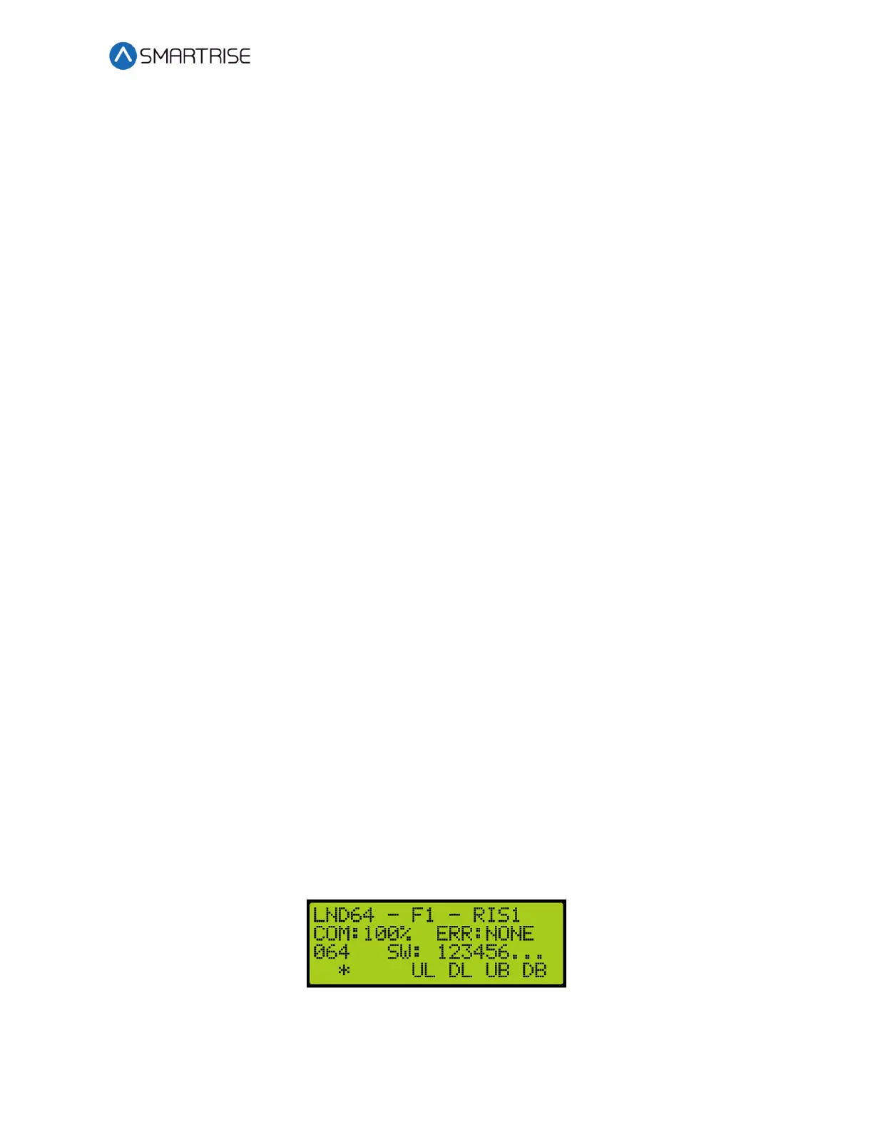
The following procedure describes how to verify Hall Lantern status.
1. Navigate to MAIN MENU | STATUS | HALL LANTERN STATUS. See Figure 47.
2. The example below shows the status of the Hall Lantern configured for the 64
th
landing.
Figure 386: Hall Lantern Status for the 64
th
Landing
 Loading...


