C4 User Manual
Page 134 ©2021 Smartrise Engineering, Inc. All Rights Reserved October 25, 2021
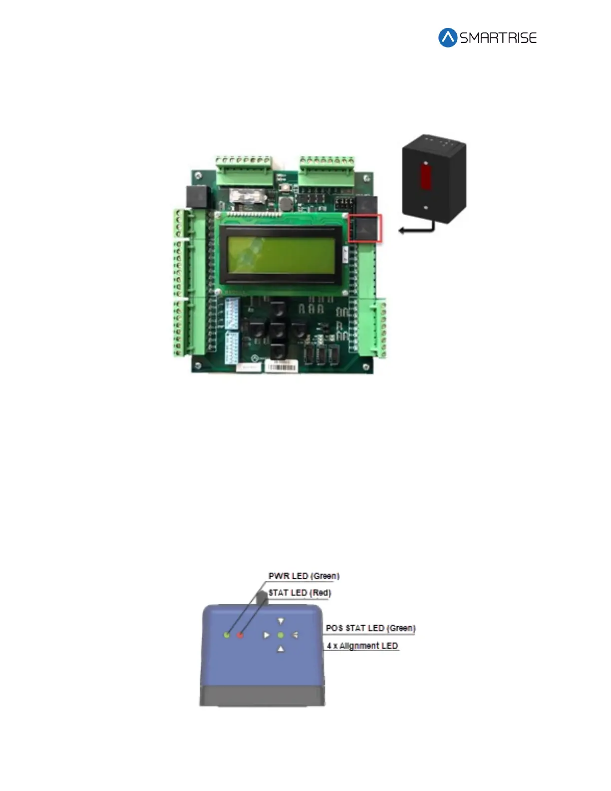
Power the APS camera via a RJ45 cable to the CT board so a red array can be seen on the tape
to allow for alignment. If there is no red array on the tape, reset the power by disconnecting
and reconnecting the RJ45 cable to the CT board CAT5 connector.
Figure 185: RJ45 Connection
Proceed on inspection up and down the hoistway and adjust each tape guide clip to the correct
in-line position with respect to the Sensor Array Assembly.
The camera powers up when the CT station is powered up.
10.9 Alignment
Alignment and Position Status LEDs are located on top of the optical sensor. These LEDs are
used to align the sensor to the tape.
Figure 186: Optical Sensor LEDs
 Loading...


