February, 2008
4-223
WorkCentre 5225, 5230
ADJ 9.1.1
Repairs and Adjustments
Launch Version
ADJ 9.1.1 IOT Lead Edge/Side Edge Registration
Purpose
To align the image on the drum with the Lead/Side Edge of the paper.
Check
1. Access Diagnostic Routines.
a. Enter UI Diagnostics (UI Diagnostic Mode).
2. Select Print Test Pattern.
3. Load A3 or 11x17 into tray 1 or 2.
NOTE: If A3 or 11x17 is not available, set the paper guides in the tray to A3 or 11x17.
Load A4 or 8.5x11 with the paper against the tray (feeder end). An error will occur but the
test print will output.
4. Enter 052-1 for tray 1 or 052-2 for tray 2 using the number key pad and press the Start
button.
NOTE: Print Test Pattern routine will auto-select the tray set with A3 or 11x17 paper
regardless of which tray is selected.
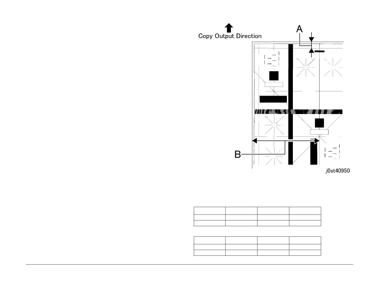
5. Measure the Lead and Side Edges of the print pattern. (Figure 1)
Lead Edge: Part A of the pattern
Side Edge: Part B of the pattern
Figure 1 IOT Registration (j0st40950)
6. Check that the measured values of the Lead Edge (A) and Side Edge (B) fall within the
specifications of the specified mode (A3 Table 1) (11x17 Table 2).
Table 1 A3 Specification
Item Simplex Duplex MPT
Lead Edge (A) 15 ± 1.3mm 15 ± 1.7mm 15 ± 2.0mm
Side Edge (B) 148.5 ± 1.8mm 148.5 ± 2.2mm 148.5 ± 2.5mm
Table 2 11x17 Specification
Item Simplex Duplex MPT
Lead Edge (A) 21 ± 1.3mm 21 ± 1.7mm 21 ± 2.0mm
Side Edge (B) 140 ± 1.8mm 140 ± 2.2mm 140 ± 2.5mm

 Loading...