February, 2008
4-131
WorkCentre 5225, 5230
REP 16.1.1, REP 16.1.2
Repairs and Adjustments
Launch Version
REP 16.1.1 H-Transport Assembly
Parts List on PL 23.1
Removal
WARNING
To avoid personal injury or shock, do not perform repair or adjustment with electrical
power applied to the machine.
1. Undock the Finisher Assembly (REP 16.2.1)
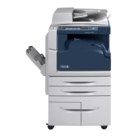
2. Move the H-Transport Assembly. (Figure 1)
a. Disconnect the cable ties and the connector.
b. Remove the screw (1).
c. Remove the Docking Plate.
d. Remove the H-Transport Assembly.
Figure 1 Removing the Docking Bracket (j0st41662.jpg)
Replacement
1. To install, carry out the removal steps in reverse order.
REP 16.1.2 Hole Punch Assembly
Parts List on PL 23.2
Removal
WARNING
To avoid personal injury or shock, do not perform repair or adjustment with electrical
power applied to the machine.
1. Open the H-Transport Top Cover and hold it open.
2. Open the H-Transport Front Cover.
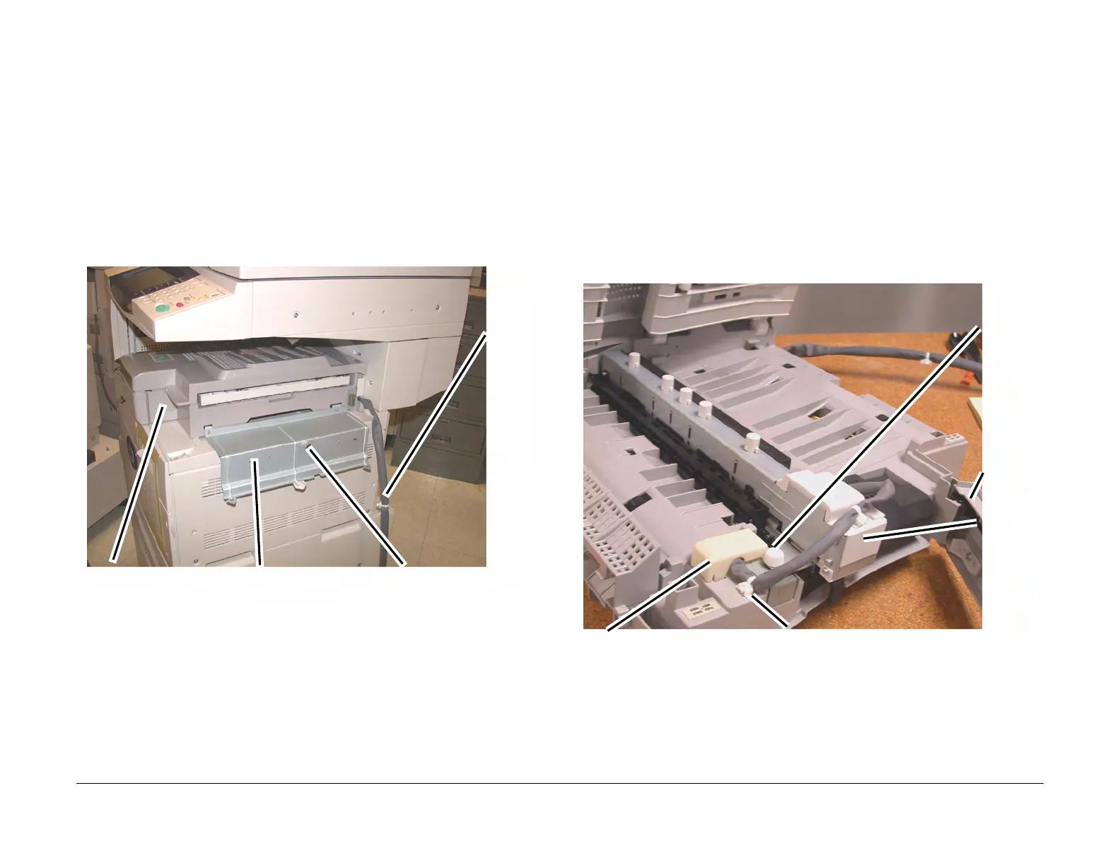
3. Remove the Hole Punch Assembly. (Figure 1)
a. Disconnect the cable clamp.
b. Remove the Connector cover and disconnect the Connector
c. Remove the Thumb screw (1).
d. Lift the Hole Punch Assembly and pull outboard to remove.
Figure 1 Removing the Hole Punch Assembly (j0st41663.jpg)
Replacement
1. Insert the Hole Punch Assembly rear locating pin into the H-Transport frame.
2. Install the Hole Punch Assembly in reverse order of removal.
1
Discon-
nect con
nector
and
Cable
2
Remove the screws (1)
3
Remove Docking Plate
4
Remove the H-Transport
2
Remove the Connector Cover and
disconnect the connector
1
Disconnect the cable
clamp
3
Remove
the
Thumb
Screw
4
Remove
the Hole
Punch
Assem-
bly
Front
Cover

 Loading...