February, 2008
4-91
WorkCentre 5225, 5230
REP 13.3.1
Repairs and Adjustments
Launch Version
REP 13.3.1 Front/Rear Tray Cable (TTM)
Parts List on PL 13.3
Removal
WARNING
To avoid personal injury or shock, do not perform repair or adjustment with electrical
power applied to the machine.
CAUTION
To prevent data loss when the power is turned off, please note the following.
FAX Models
Check that the “Stored Documents” lamp is not on, and press the Job Status button to ensure
that there are no jobs in progress.
Printer Models
Check that “Ready to Print/Send” is displayed on the Control Panel display.
1. Remove the Tray 4 Assembly. (REP 13.1.2)
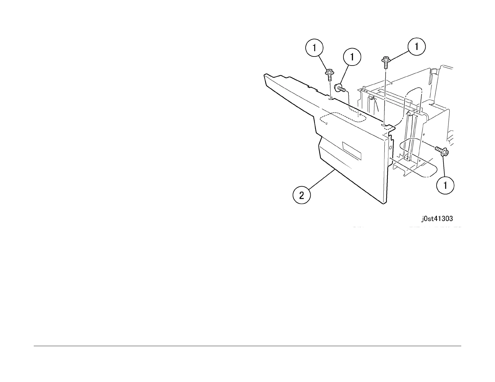
2. Remove the Tray 4 Cover together with the frame.(Figure 1)
1. Remove the screws (x4).
2. Remove the Tray 4 Cover together with the frame.
Figure 1 Removing the Tray 4 Cover (j0st41303)
3. Remove the Tray Cable. (Figure 2)
NOTE: Only the replacement procedure for the Front Tray Cable is described here. The
Rear Tray Cable is removed in the same way.
1. Remove the E-Clip.
2. Remove the Cable Guide.
3. Remove the Tray Cable.
4. Remove the E-Clip.
5. Remove the Cable Guide.
6. Remove the Tray Cable.

 Loading...