February, 2008
4-148
WorkCentre 5225, 5230
REP 16.2.13
Launch Version
Repairs and Adjustments
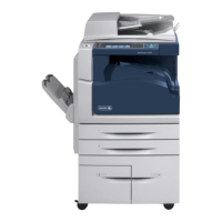
Figure 9 Removing the Set Clamp Shaft (j0st41725)
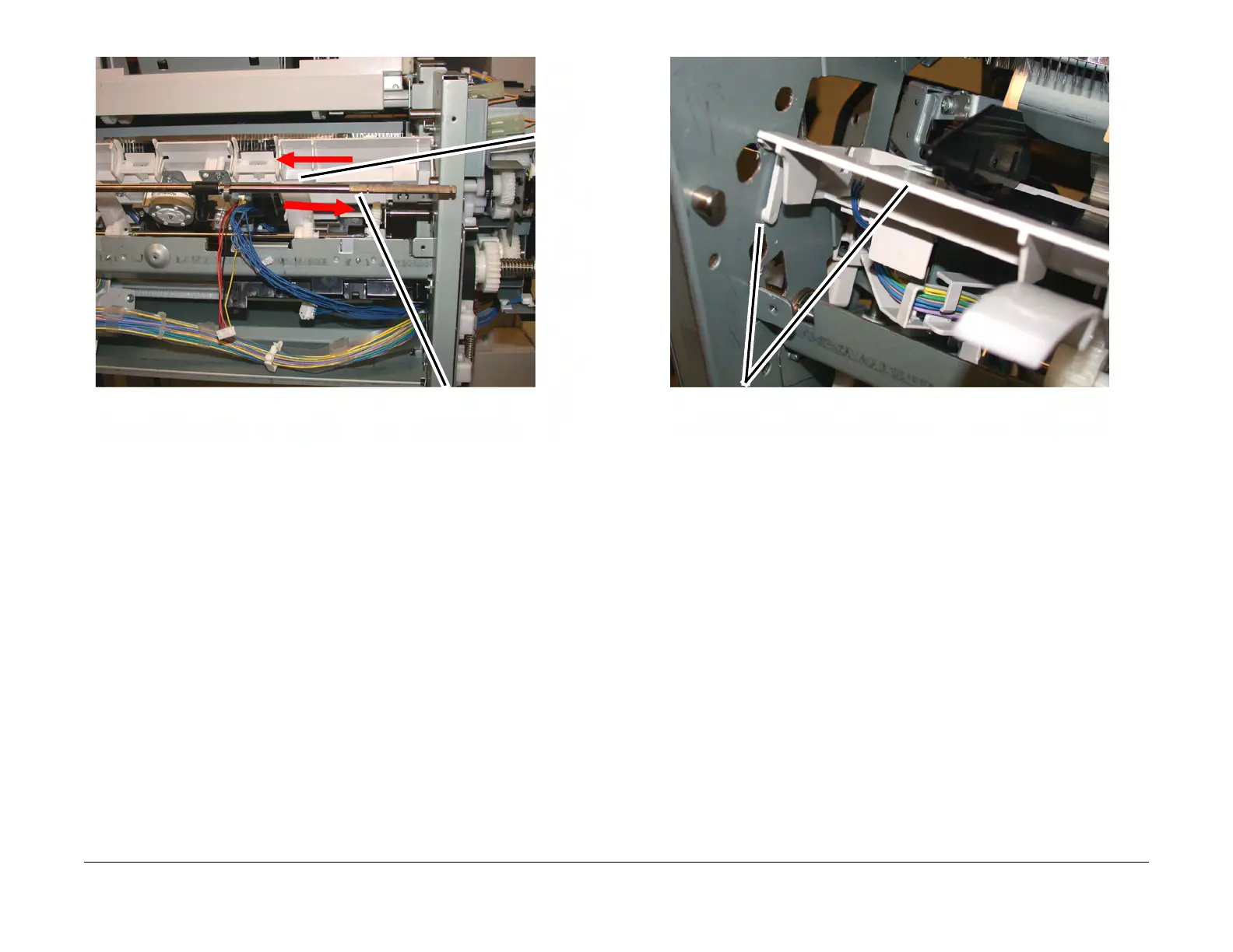
18. Remove the Compiler Tray Assembly. (Figure 10)
Figure 10 Remove the Compiler Tray Assembly (j0st41723)
19. Usually this level of Compiler Tray Assembly removal is for the purpose of removing the
Front or Rear Tamper Motors, or the Front or Rear Tamper Home Sensors or the Com
-
piler Tray No Paper Sensor.
However if the Compiler Tray Assembly must be completely removed from the Finisher, it
will be necessary to disconnect all of the wire harness connectors to the Tamper Motors,
Tamper Home Sensors and No Paper Sensor and disconnect the wires from all wire har
-
ness guides.
Replacement
1. Route the wire harness through the wire guides and connect the proper connectors to the
No Paper Sensor, the Tamper Home Sensors and the Tamper Motors.
2. Place the Compiler Tray Assembly into position.
3. Install the Set Clamp Shaft front end into the front frame. (Figure 11)
4. Slide the Shaft toward the front until the rear end of the Shaft can be inserted into the rear
frame. (Figure 11)
1
Slide the
Shaft
toward
the front
2
Slide the Shaft toward
the rear and remove
Remove the Compiler
Tray Assembly

 Loading...