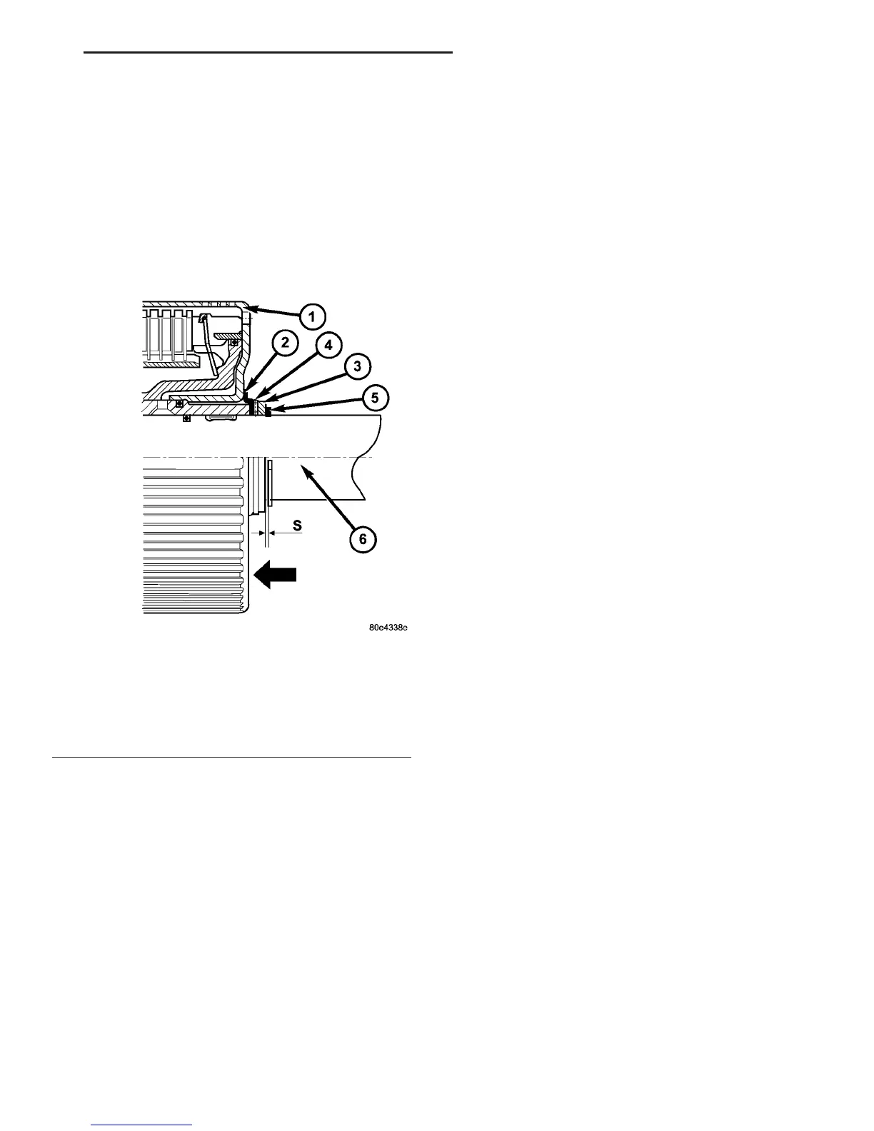
(8) Inspect axial play (Fig. 203) between shim (10)
and retaining ring (11). Check axial play 9S9 between
shim (10) and retaining ring (1) using a feeler gauge.
Clearance should be 0.15-0.6 mm (0.006-0.024 in.).
Shims are available in thicknesses of 3.0 mm (0.118
in.), 3.4 mm (0.134 in.), and 3.7 mm (0.146 in.).
Adjust as necessary
NOTE: During the test, apply a contact force by
hand to K3 in the direction of the arrow.
SHIFT MECHANISM
DESCRIPTION
The automatic transmission is operated with the
help of a shift lever assembly (SLA) located in the
center console. There are four positions to which the
selection lever can be shifted: P, R, N, D. In addition,
the selector lever can be moved sideways (+/-) in posi-
tion 9D9 to adjust the shift range.
All selector lever positions, as well as selected shift
ranges in position 9D9, are identified by the SLA. The
information is then sent to the transmission control
module (TCM) via a hardwire connection. At the
same time, the selector lever positions 9P9, 9R9, 9N9
and 9D9 are transmitted by a shift cable to the selec-
tor shaft in the transmission.
The SLA is comprised of the following functions:
• Key lock: Depending on the selector lever posi-
tion, the ignition lock is locked/unlocked, i.e., the
ignition key can be removed only if the selector lever
is in position 9P9. A park lock cable is used to perform
this function.
• Park lock: The selector lever is not released
from postion 9P9 until the brake pedal has been
applied and the ignition key is in driving position.
Shift lock is controlled by the brake light switch in
conjunction with a locking solenoid in the SLA. As
soon as the brake pedal is applied firmly, the locking
solenoid is retracted to unlock the selector lever. If
the selector lever cannot be moved out of position 9P9
due to a malfunction, the shift lock function can be
overriden (see operator’s manual).
• Reverse inhibitor: As soon as the vehicle
speed exceeds approx. 4 mph, it is no longer possible
to move the selector lever from position 9N9 to posi-
tion 9R9.
OPERATION
With the selector lever in position 9D9, the trans-
mission control module (TCM) automatically shifts
the gears that are best-suited to the current operat-
ing situation. This means that shifting of gears is
continuously adjusted to current driving and operat-
ing conditions in line with the selected shift range
and the accelerator pedal position. Starting off is
always performed in 1st gear.
The selector lever positions are determined by the
slider position of a potentiometer in the shift lever
assembly (SLA). The shift pattern diagram (position
display) and the program selector are illuminated by
the LEDs.
The current selector lever position or, if the shift
range has been limited, the current shift range is
indicated in the LCD display in the instrument clus-
ter.
The permissible shifter positions and transmission
operating ranges are:
• P = Parking lock and engine starting.
• R = Reverse.
• N = Neutral and engine starting (no power is
transmitted to the axles).
• D = The shift range includes all forward gears.
• 4= Shift range is limited to gears 1 to 4.
• 3= Shift range is limited to gears 1 to 3.
• 2= Shift range is limited to gears 1 to 2.
• 1= Shift range is limited to the 1st gear.
The shift range can be adjusted to the current
operating conditions by tipping the selector lever to
the left-hand side (9-9) or the right-hand side (9+9)
when in position 9D9. If the shift range is limited, the
display in the instrument cluster indicates the
selected shift range and not the currently engaged
gear.
Fig. 203 Check Center and Rear Planetary End-Play
1 - DRIVING CLUTCH K3
2 - THRUST WASHER
3 - SHIM
4 - AXIAL NEEDLE BEARING
5 - RETAINING RING
6 - OUTPUT SHAFT WITH CENTER PLANETARY CARRIER
VA AUTOMATIC TRANSMISSION - NAG1 21 - 133
PLANETARY GEARTRAIN (Continued)

 Loading...


