(2) Position the boost pressure sensor above access
hole in the charge air pipe and push down to fit flush
(Fig. 3).
(3) Install the bolts and tighten to 44 lbs. in. (5
N·m) (Fig. 3).
(4) Reconnect the sensor electrical connector (Fig.
3).
(5) Connect negative battery cable
CAMSHAFT POSITION
SENSOR
DESCRIPTION
The camshaft position sensor is mounted on the
cylinder head cover toward the rear of the engine.
The camshaft sensor utilizes a non contact method
on one segment of the camshaft to record the cam-
shaft position. When the ECM receives the signal
from this sensor, it can then detect TDC of cylinder
number one. The signal from the camshaft sensor is
only required during engine starting. Injection timing
is synchronized by means of the camshaft signal and
the crankshaft signal.
OPERATION
On the camshaft sensor’s signal line, a high signal
correspons to a voltage of 11–14V. If the segment
machined into the exhaust camshaft sprocket is posi-
tioned opposite the camshaft sensor, the camshaft
signal is low, approximately 0V. This signal is used
by the engine control module (ECM) for detecting
ignition TDC of cylinder 1 as the engine rotates. If no
signal is supplied by the camshaft position sensor,
the vehicle will not start because cylinder order can
not be detected (Fig. 4).
REMOVAL
(1) Disconnect negative battery cable.
(2) Remove engine cover
(3) Disconnect camshaft position sensor electrical
connector (Fig. 5).
(4) Remove retaining bolt and remove sensor (Fig.
5).
INSTALLATION
(1) Install camshaft position sensor and tighten
bolt (Fig. 5).
(2) Reconnect electrical connector (Fig. 5).
(3) Install engine cover.
(4) Reconnect negative battery cable.
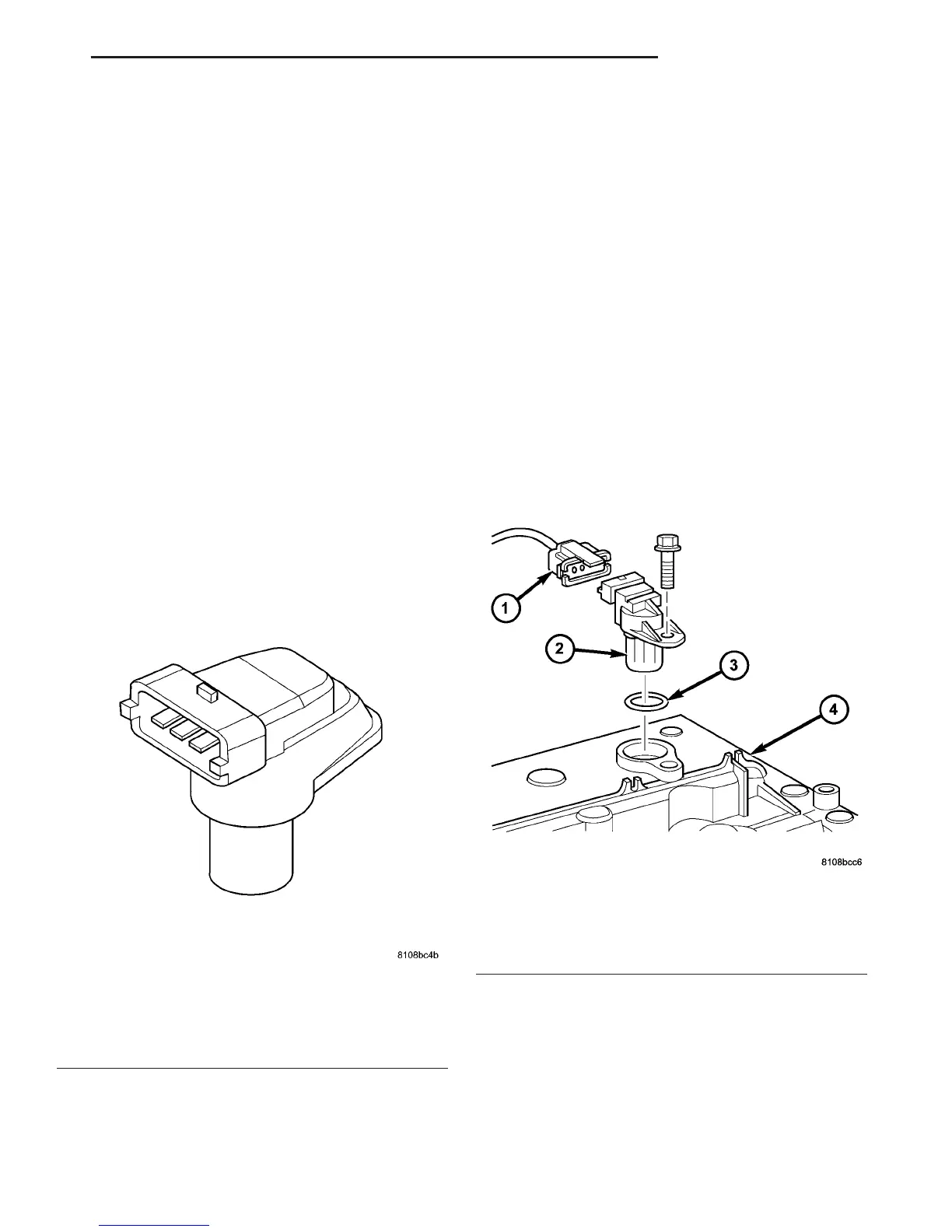
Fig. 4 CAMSHAFT POSITION SENSOR
1 - WIRING HARNESS CONNECTOR
2 - CAM POSITION SENSOR
3 - O-RING
4 - CYLINDER HEAD COVER
Fig. 5 CAM POSITION SENSOR
1 - WIRING HARNESS CONNECTOR
2 - CAM POSITION SENSOR
3 - O-RING
4 - CYLINDER HEAD COVER
VA FUEL INJECTION 14 - 19
BOOST PRESSURE SENSOR (Continued)

 Loading...


