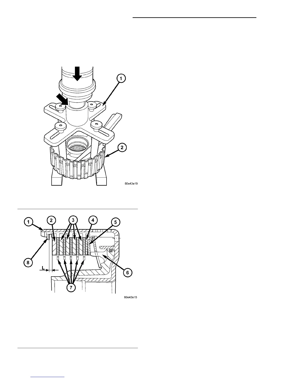
(f) Adjust with snap-ring (8), if necessary. Snap-
rings are available in thicknesses of 2.0 mm (0.079
in.), 2.3 mm (0.091 in.), 2.6 mm (0.102 in.), 2.9 mm
(0.114 in.), 3.2 mm (0.126 in.), and 3.5 mm (0.138
in.).
ELECTROHYDRAULIC UNIT
DESCRIPTION
The electrohydraulic control unit comprises the
shift plate made from light alloy for the hydraulic
control and an electrical control unit. The electrical
control unit comprises of a supporting body made of
plastic, into which the electrical components are
assembled. The supporting body is mounted on the
shift plate and screwed to it.
Strip conductors inserted into the supporting body
make the connection between the electrical compo-
nents and a plug connector. The connection to the
wiring harness on the vehicle and the transmission
control module (TCM) is produced via this 13-pin
plug connector with a bayonet lock.
ELECTRICAL CONTROL UNIT
The electric valve control unit (7) (Fig. 88) consists
of a plastic shell which houses the RPM sensors
(1,12), regulating solenoid valves (3, 4), solenoid
valves (5, 6, 10), the TCC solenoid valve (11), the
park/neutral contact (9), and the transmission oil
temperature sensor (8). Conductor tracks integrated
into the shell connect the electric components to a
plug connection (2). This 13-pin plug connection (2)
establishes the connection to the vehicle-side cable
harness and to the transmission control module
(TCM). With the exception of the solenoid valves, all
other electric components are fixed to the conductor
tracks.
HYDRAULIC CONTROL UNIT
Working Pressure (Operating Pressure) (p-A)
The working pressure provides the pressure supply
to the hydraulic control and the transmission shift
elements. It is the highest hydraulic pressure in the
entire hydraulic system. The working pressure is reg-
ulated at the working pressure regulating valve in
relation to the load and gear. All other pressures
required for the transmission control are derived
from the working pressure.
Lubrication Pressure (p-Sm)
At the working pressure regulating valve surplus
oil is diverted to the lubrication pressure regulating
valve, from where it is used in regulated amounts to
lubricate and cool the mechanical transmission com-
ponents and the torque converter. Furthermore, the
lubrication pressure (p-Sm) is also used to limit the
pressure in the torque converter.
Fig. 86 Measure K3 Clutch Clearance
1 - PRESSING TOOL 8901
2 - OUTER DISC CARRIER
Fig. 87 Driving Clutch K3 Stack-up
1 - OUTER DISC CARRIER
2 - OUTER MULTIPLE DISC - 4.0 MM (0.158 IN.)
3 - OUTER MULTIPLE DISC - 2.8 MM (0.110 IN.)
4 - OUTER MULTIPLE DISC - 1.8 MM (0.079 IN.)
5 - DISC SPRING
6 - PISTON
7 - FRICTION DISCS - 2.1 MM (0.083 IN.)
8 - SNAP-RING
21 - 82 AUTOMATIC TRANSMISSION - NAG1 VA
DRIVING CLUTCH K3 (Continued)

 Loading...


