WARNING: USE EXTREME CAUTION WHEN THE
ENGINE IS OPERATING. DO NOT STAND IN A
DIRECT LINE WITH THE FAN. DO NOT PUT YOUR
HANDS NEAR THE PULLEYS, BELTS OR FAN. DO
NOT WEAR LOOSE CLOTHING.
(14) Start engine and inspect for leaks.Care must
be taken to observe the fuel system warning (Refer to
14 - FUEL SYSTEM - WARNING).
(15) Install engine cover (Refer to 9 - ENGINE
COVER - INSTALLATION).
CYLINDER HEAD COVER(S)
REMOVAL
(1) Disconnect negative battery cable.
(2) Disconnect the air inlet and set aside.
(3) Detach hose from oil separator.
(4) Disconnect the camshaft position sensor.
(5) Disconnect fuel injector and glow plug harness
and set aside.
(6) Remove fuel high pressure pipes and injectors
(Refer to 14 - FUEL SYSTEM/FUEL INJECTION/
FUEL INJECTOR - REMOVAL).
(7) Disconnect the out let line.
(8) Remove cylinder head cover retaining bolts and
remove cover (Fig. 21).
INSTALLATION
NOTE: Do Not tighten the cylinder head cover first.
The fuel injectors are aligned by way of the cylinder
head cover.
(1) Fit cylinder head cover with new gasket and
install bolts (Fig. 21).
(2) Insert all fuel injectors and tensioning claws.
Insert new bolts and tighten in the following order:
3, 4, 5, 2, 1.(Refer to 14 - FUEL SYSTEM/FUEL
INJECTION/FUEL INJECTOR - INSTALLATION).
(3) Tighten cylinder head cover bolts to 9 N·m (80
lbs. in.).
(4) Install and properly route fuel injector and
glow plug wiring harness, making appropriate con-
nections.
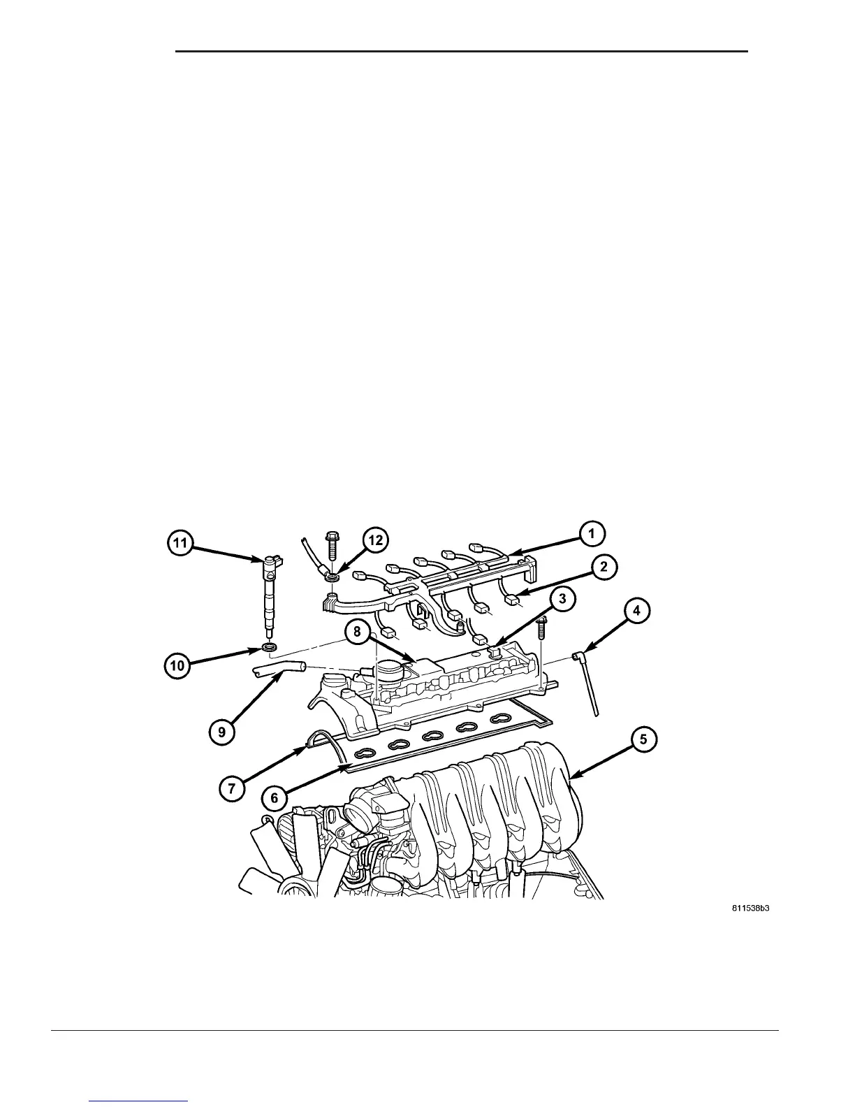
Fig. 21 CYLINDER HEAD COVER
1 - ENGINE WIRING HARNESS 7 - GASKET
2 - GLOW PLUG CONNECTOR 8 - CYLINDER HEAD COVER
3 - CAMSHAFT POSITION SENSOR 9 - CRANKCASE VENT LINE
4 - OUTLET LINE 10 - GASKET
5 - INTAKE MANIFOLD 11 - FUEL INJECTOR
6 - GASKET 12 - GROUND
9 - 30 ENGINE VA
CAMSHAFT(S) (Continued)

 Loading...


