GEAR
TABLE OF CONTENTS
page page
GEAR
DESCRIPTION ..........................8
REMOVAL .............................8
INSTALLATION ..........................8
SPECIFICATIONS - TORQUE CHART .........9
GEAR
DESCRIPTION
A rack and pinion steering gears (Fig. 1) is made
up of two main components, the pinon shaft and the
rack. The gear cannot be adjusted or internally ser-
viced. If a malfunction or a fluid leak occurs, the gear
must be replaced as an assembly.
REMOVAL
(1) Siphon the power steering fluid out of the res-
ervoir.
(2) Raise and support the vehicle.
(3) Remove the front wheels.
(4) Remove the stabilizer bar from the upper part
of the stabilizer link (Refer to 2 - SUSPENSION/
FRONT/STABILIZER LINK - REMOVAL).
(5) Remove the outer tie rod end nuts and sepa-
rate the tie rods from the steering knuckles (Fig. 2)
using special tool C-3894–A.
(6) Remove the left outer tie rod end from the
steering gear.
(7) Remove both spring clamp plates (Refer to 2 -
SUSPENSION/FRONT/SPRING CLAMP PLATES -
REMOVAL).
(8) Remove both the high pressure and return
hoses from the steering gear (Refer to 19 - STEER-
ING/PUMP/HOSES - REMOVAL) (Fig. 2).
(9) Remove the steering shaft clamping bolt from
the steering gear (Fig. 2).
(10) Separate the universal joint from the steering
gear (Fig. 2).
(11) Remove the steering gear bolts from the front
axle.
(12) Remove the steering gear by sliding it toward
the passengers side of the vehicle and then tilt down-
ward on the drivers side and remove from vehicle.
INSTALLATION
(1) Install the gear to the vehicle.
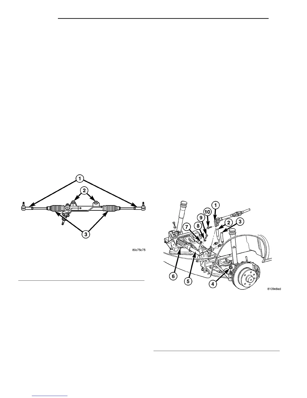
Fig. 1 STEERING GEAR
1 - OUTER TIE ROD ENDS
2 - MOUNTING BUSHINGS
3 - BELLOWS
Fig. 2 STEERING GEAR REMOVAL / INSTALL
1 - U-JOINT
2 - HIGH PRESSURE POWER STEERING HOSE
3 - RETURN HOSE
4 - OUTER TIE ROD END RETAINING NUT
5 - STEERING GEAR
6 - STEERING GEAR RETAINING BOLT
7 - STEERING GEAR NUT
8 - WASHER
9 - ENGINE MOUNT BOLT
10 - U-JOINT CLAMPING BOLT
19 - 8 GEAR VA

 Loading...


