(14) Remove the inlet and exhaust camshafts (Fig.
20).
INSTALLATION
CAUTION: The camshafts are sensitive to fractur-
ing. Ensure they are installed free of stress.
CAUTION: Pay attention to assignment of cam-
shafts. Camshaft code numbers are visible on the
thrust collar of the axial bearing.
CAUTION: Oil bucket tappets and camshaft bearing
points. Inspect ease of operation of bucket tappets.
(1) Install inlet and exhaust camshafts.
CAUTION: Install camshafts so that the two holes in
camshaft sprockets are positioned opposite and the
markings of the camshaft and camshaft bearing cap
are aligned.
(2) Align inlet and exhaust camshafts at axial
bearing (Refer to 9 - ENGINE/CYLINDER HEAD/
CAMSHAFT(S) - STANDARD PROCEDURE).
NOTE: Pay attention to markings on camshaft bear-
ing caps.
CAUTION: Do not rotate engine counter clockwise.
(3) Position the piston of cylinder #1 to ignition
TDC.
NOTE: Pay attention to markings on camshaft bear-
ing caps.
(4) Install the bearing caps in reverse order at the
same point. Tighten bearing cap bolts evenly to 9N·m
(80 lbs. in.) in steps each of 1 turn.
NOTE: The piston of cylinder #1 must be positioned
at ignition TDC when the inlet camshaft is locked.
(5) Insert locking pin through the first camshaft
bearing cap into the whole in the camshaft sprocket.
NOTE: Do Not use old camshaft sprocket bolts.
(6) Fit camshaft sprocket with timing chain fitted
on, onto exhaust camshaft paying attention to posi-
tion of dowel pin. Tighten bolt to 18N·m (159 lbs.in.).
(7) Install timing chain tensioner (Refer to 9 -
ENGINE/VALVE TIMING/TIMING BELT/CHAIN
AND SPROCKETS - INSTALLATION).
(8) Inspect/Set basic position of camshafts (Refer
to 9 - ENGINE/CYLINDER HEAD/CAMSHAFT(S) -
STANDARD PROCEDURE).
(9) Insert slide rail and bolt the driver into the
inlet camshaft. Tighten bolt driver to 50N·m (37 lbs.
in.).
(10) Install front cover at cylinder head.
(11) Install cylinder head cover (Refer to 9 -
ENGINE/CYLINDER HEAD/CYLINDER HEAD
COVER(S) - INSTALLATION).
NOTE: Refer to the appropriate injector servicing
procedures for cleaning of injectors and recesses.
(12) Clean and install injectors (Refer to 14 -
FUEL SYSTEM/FUEL INJECTION/FUEL INJEC-
TOR - STANDARD PROCEDURE), (Refer to 14 -
FUEL SYSTEM/FUEL INJECTION/FUEL INJEC-
TOR - INSTALLATION).
(13) Reconnect negative battery cable.
WARNING: (Refer to 14 - FUEL SYSTEM - WARN-
ING).
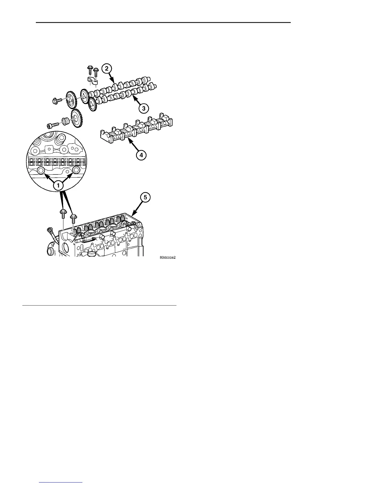
Fig. 20 CAMSHAFTS AND HOUSING ASSEMBLY
1 - CYLINDER HEAD BOLTS
2 - EXHAUST CAMSHAFT
3 - INTAKE CAMSHAFT
4 - CAMSHAFT HOUSING
5 - CYLINDER HEAD
VA ENGINE 9 - 29
CAMSHAFT(S) (Continued)

 Loading...


