(12) Remove the strainers for the modulating pres-
sure and shift pressure control solenoid valves (Fig.
116) from the valve housing.
(13) Remove the strainer (1) (Fig. 117) in the inlet
to torque converter lock-up control solenoid valve.
(14) Remove sealing plate (3).
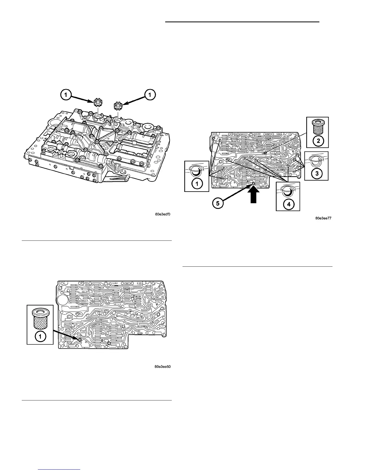
NOTE: A total of 12 valve balls are located in the
valve body, four made from plastic (4) and eight
from steel (1, 3).
(15) Note the location of all check balls (1, 3, 4)
(Fig. 118) and the central strainer (2) for re-installa-
tion. Remove all check balls (1, 3, 4) and the central
strainer (2).
(16) Remove the screws holding the side covers to
the valve body and valve housing.
(17) Remove all valves and springs from the valve
body (1) (Fig. 119). Check all valves for ease of move-
ment and shavings.
NOTE: The sleeves and pistons of the overlap reg-
ulating valves must not be mixed up.
(18) Remove all valves and springs from the valve
housing (2) (Fig. 120). Check all valves for ease of
movement and shavings.
(19) Remove the pressure supply valve (1) (Fig.
121) from the valve body.
Fig. 116 Solenoid Valve Strainer Locations
1 - SOLENOID VALVE STRAINERS
Fig. 117 Converter Lock-up Solenoid Valve Strainer
Location
1 - CONVERTER LOCK-UP SOLENOID STRAINER
Fig. 118 Check Balls and Strainer Location
1 - STEEL CHECK BALLS
2 - CENTRAL STRAINER
3 - STEEL CHECK BALLS
4 - PLASTIC CHECK BALLS
5 - PLAIN DOWEL PIN
21 - 94 AUTOMATIC TRANSMISSION - NAG1 VA
ELECTROHYDRAULIC UNIT (Continued)

 Loading...


