nosed and tested using conventional diagnostic tools
and procedures. However, conventional diagnostic
methods will not prove conclusive in the diagnosis of
the ACM or the supplemental restraint system. The
most reliable, efficient, and accurate means to diag-
nose the ACM or the supplemental restraint system
requires the use of a DRBIIIt scan tool. Refer to the
appropriate diagnostic information.
REMOVAL
WARNING: ON VEHICLES EQUIPPED WITH AIR-
BAGS, DISABLE THE SUPPLEMENTAL RESTRAINT
SYSTEM BEFORE ATTEMPTING ANY STEERING
WHEEL, STEERING COLUMN, DRIVER AIRBAG,
PASSENGER AIRBAG, SEAT BELT TENSIONER, OR
INSTRUMENT PANEL COMPONENT DIAGNOSIS OR
SERVICE. DISCONNECT AND ISOLATE THE BAT-
TERY NEGATIVE (GROUND) CABLE, THEN WAIT
TWO MINUTES FOR THE SYSTEM CAPACITOR TO
DISCHARGE BEFORE PERFORMING FURTHER
DIAGNOSIS OR SERVICE. THIS IS THE ONLY SURE
WAY TO DISABLE THE SUPPLEMENTAL
RESTRAINT SYSTEM. FAILURE TO TAKE THE
PROPER PRECAUTIONS COULD RESULT IN ACCI-
DENTAL AIRBAG DEPLOYMENT AND POSSIBLE
PERSONAL INJURY.
WARNING: THE AIRBAG CONTROL MODULE CON-
TAINS THE IMPACT SENSOR, WHICH ENABLES
THE SYSTEM TO DEPLOY THE SUPPLEMENTAL
RESTRAINTS. NEVER STRIKE OR DROP THE AIR-
BAG CONTROL MODULE, AS IT CAN DAMAGE THE
IMPACT SENSOR OR AFFECT ITS CALIBRATION. IF
AN AIRBAG CONTROL MODULE IS ACCIDENTALLY
DROPPED DURING SERVICE, THE MODULE MUST
BE SCRAPPED AND REPLACED WITH A NEW UNIT.
FAILURE TO OBSERVE THIS WARNING COULD
RESULT IN ACCIDENTAL, INCOMPLETE, OR
IMPROPER SUPPLEMENTAL RESTRAINT DEPLOY-
MENT AND POSSIBLE OCCUPANT INJURIES.
(1) Disconnect and isolate the battery negative
cable. Wait two minutes for the system capacitor to
discharge before further service.
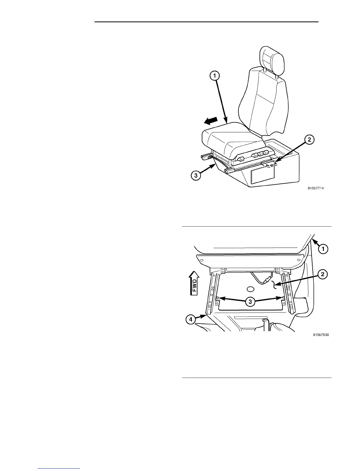
(2) Move the driver side front seat to its most for-
ward position for easiest access to the seat riser
cover panel (Fig. 8).
(3) Remove the two screws that secure the cover
panel to the top of the seat riser under the driver
side front seat (Fig. 9).
(4) Remove the cover panel from the top of the
driver side seat riser.
(5) Remove the two screws that secure the control
module bracket to the top of the seat riser under the
driver side front seat (Fig. 10).
(6) Remove the control module bracket from the
top of the driver side seat riser.
(7) Locate the Airbag Control Module (ACM) in the
right rear corner of the area within the driver side
seat riser. Firmly grasp and pull upward on the
molded plastic cover to unsnap it from over the ACM
(Fig. 11).
Fig. 8 Airbag Control Module Location
1 - DRIVER SEAT
2 - AIRBAG CONTROL MODULE
3 - SEAT RISER
Fig. 9 Seat Riser Cover
1 - DRIVER SEAT BACK
2 - COVER PANEL
3 - SCREW (2)
4 - SEAT RISER
8O - 10 RESTRAINTS VA
AIRBAG CONTROL MODULE (Continued)

 Loading...


