(8) Position and install the oil pan. Tighten M6
bolts to 9 N·m (80 lbs in) and M8 bolts to 20 N·m
(177 lbs in).
(9) Install belt /pulley vibration damper. Tighten
M8.8 bolt in two stages, 200N·m (147 lbs ft.) then
90°, M10.9 bolt 325N·m (240 lbs ft) then 90°.
(10) Remove the engine support fixture.
(11) Install generator (Refer to 8 - ELECTRICAL/
CHARGING/GENERATOR - INSTALLATION).
(12) Install the air conditioning compressor.
(13) Install the power steering pump.
(14) Install water pump (Refer to 7 - COOLING/
ENGINE/WATER PUMP - INSTALLATION).
(15) Connect coolant hose to oil-water heat
exchanger.
(16) Install high pressure fuel pump (Refer to 14 -
FUEL SYSTEM/FUEL DELIVERY/FUEL PUMP -
INSTALLATION).
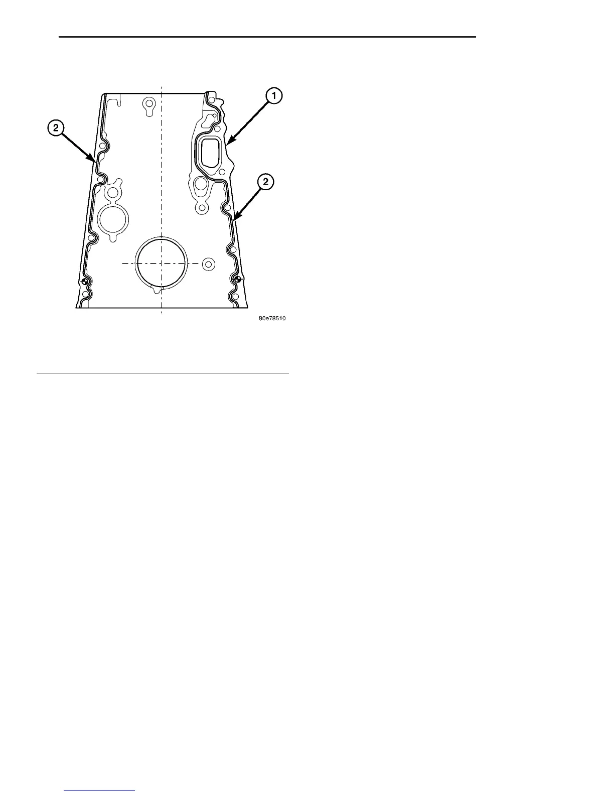
(17) Apply sealant to lower portion of, and install,
front cover to cylinder block. Tighten bolts to 20N·m
(177 lbs in) (Refer to 9 - ENGINE/CYLINDER HEAD
- INSTALLATION).
(18) Remove retaining lock for crankshaft/starter
ring gear.
(19) Tighten the oil drain plug to 30N·m (265 lbs
in).
(20) Install a new oil filter. tighten screw cap for
filter to 25N·m (221 lbs. in.).
(21) Install the accessory drive belt.
(22) Install the radiator assembly (Refer to 7 -
COOLING/ENGINE/RADIATOR - INSTALLATION).
(23) Install air intake hose.
(24) Fill coolant to the proper level, with the
proper coolant (Refer to 7 - COOLING/ENGINE/
COOLANT - STANDARD PROCEDURE).
(25) Fill the crankcase with the correct oil, to the
proper level. Refer to owners manual for specifica-
tions.
(26) Connect the negative battery cable.
WARNING: USE EXTREME CAUTION WHEN THE
ENGINE IS OPERATING. DO NOT STAND IN A
DIRECT LINE WITH THE FAN. DO NOT PUT YOUR
HANDS NEAR THE PULLEYS, BELTS OR FAN. DO
NOT WEAR LOOSE CLOTHES.
CAUTION: DO NOT pressure test cooling system
until the engine reaches operating temperature.
(27) Start engine and inspect for leaks. care must
be taken to observe the fuel system warning (Refer to
14 - FUEL SYSTEM - WARNING).
TIMING BELT/CHAIN AND
SPROCKETS
REMOVAL
REMOVAL - TENSIONING AND SLIDE RAILS
NOTE: If it necessary to replace the tensioning rail,
slide rail or tensioning arm, they are always
replaced together.
(1) Disconnect negative battery cable.
(2) Remove the engine (Refer to 9 - ENGINE -
REMOVAL).
(3) Remove cylinder head (Refer to 9 - ENGINE/
CYLINDER HEAD - REMOVAL).
NOTE: Remove timing case cover carefully. Care
must be taken not to damage oil pan gasket.
(4) Remove timing case cover (Refer to 9 -
ENGINE/VALVE TIMING/TIMING BELT / CHAIN
COVER(S) - REMOVAL).
(5) Pull the tensioning rail off of the bearing pins
(Fig. 67).
(6) Release the spring at the slide rail and take it
off of the tensioning arm (Fig. 67).
REMOVAL - INTERMEDIATE GEAR
(1) Disconnect negative battery cable.
(2) Remove engine cover (Refer to 9 - ENGINE -
REMOVAL).
Fig. 66 TIMING CHAIN COVER SEALING SURFACE
1 - TIMING CHAIN COVER
2 - SEALANT BEAD
VA ENGINE 9 - 61
TIMING CHAIN COVER (Continued)

 Loading...


