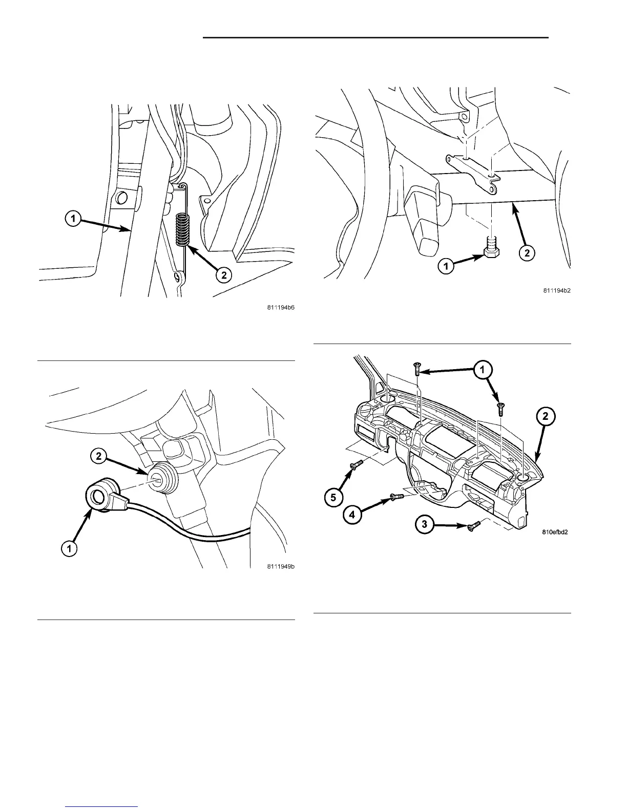
(22) Remove brake pedal spring. (Fig. 17)
(23) Remove ignition transponder. (Fig. 18)
CAUTION: The position of the steering gear must
not be altered again for the entire duration of the
work procedure.
(24) Turn the steering wheel and lock the steering
wheel in the straight ahead position.
(25) Remove steering column support bolts. (Fig.
19)
(26) Remove the screws and remove instrument
panel. (Fig. 20)
Fig. 17 BRAKE PEDAL SPRING
1 - STEERING COLUMN
2 - SPRING
Fig. 18 IGNITION TRANSPONDER
1 - COLUMN LOCK
2 - IGNITION TRANSPONDER
Fig. 19 STEERING COLUMN BOLTS
1 - BOLTS (2)
2 - STEERING COLUMN
Fig. 20 INSTRUMENT PANEL FASTENERS
1 - UPPER SCREWS (6)
2 - INSTRUMENT PANEL
3 - RIGHT SCREW
4 - CENTER SCREWS (2)
5 - LEFT SCREWS (3)
23 - 60 INSTRUMENT PANEL VA
INSTRUMENT PANEL ASSEMBLY (Continued)

 Loading...


