DRIVELINE VIBRATION
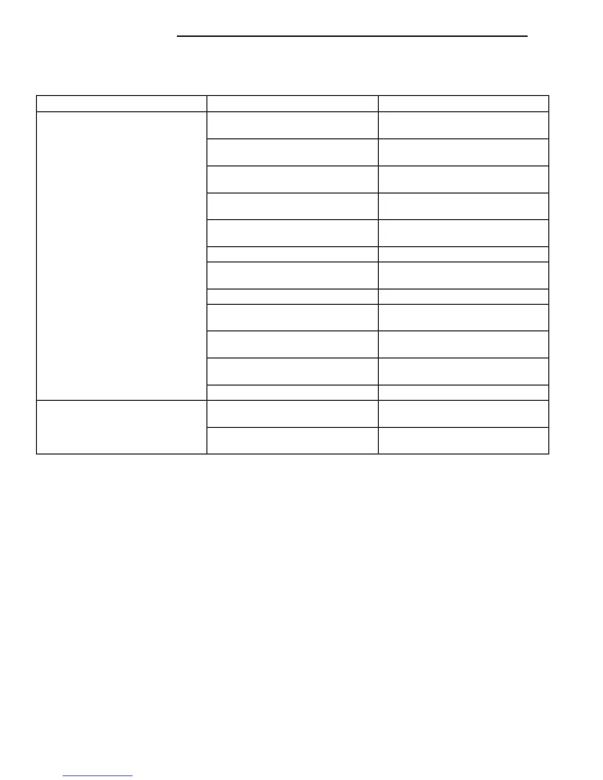
Drive Condition Possible Cause Correction
Propeller Shaft Noise 1) Undercoating or other foreign
material on shaft.
1) Clean exterior of shaft and wash
with solvent.
2) Loose U-joint clamp screws. 2) Install new clamps and screws
and tighten to proper torque.
3) Loose or bent U-joint yoke or
excessive runout.
3) Install new yoke.
4) Incorrect driveline angularity. 4) Measure and correct driveline
angles.
5) Rear spring center bolt not in
seat.
5) Loosen spring u-bolts and seat
center bolt.
6) Worn U-joint bearings. 6) Install new U-joint.
7) Propeller shaft damaged or out
of balance.
7) Installl new propeller shaft.
8) Broken rear spring. 8) Install new rear spring.
9) Excessive runout or unbalanced
condition.
9) Re-index propeller shaft, test,
and evaluate.
10) Excessive drive pinion gear
shaft runout.
10) Re-index propeller shaft and
evaluate.
11) Excessive axle yoke deflection. 11) Inspect and replace yoke if
necessary.
12) Excessive transfer case runout. 12) Inspect and repair as necessary.
Universal Joint Noise 1) Loose U-joint clamp screws. 1) Install new clamps and screws
and tighten to proper torque.
2) Lack of lubrication. 2) Replace as U-joints as
necessary.
PROPELLER SHAFT BALANCE
NOTE: Removing and indexing the propeller shaft
180° relative to the yoke may eliminate some vibra-
tions.
If propeller shaft is suspected of being out of bal-
ance, verify with the following procedure:
(1) Place vehicle in netrual.
(2) Raise and support the vehicle by the axles as
level as possible.
(3) Clean all foreign material from propeller shaft
and universal joints.
(4) Inspect propeller shaft for missing balance
weights, broken welds, and bent areas.
NOTE: If propeller shaft is bent, it must be replaced.
(5) Inspect universal joints for wear, properly
installed and correct alignment with the shaft.
(6) Check universal joint clamp screws torque.
(7) Remove wheels and tires. Install wheel lug
nuts to retain the brake drums/rotors.
(8) Mark and number propeller shaft six inches
from the pinion yoke end at four positions 90° apart.
(9) Run and accelerate the vehicle until vibration
occurs. Note intensity and speed the vibration
occurred. Stop the engine.
(10) Install a screw clamp at position 1 (Fig. 1).
(11) Start engine and re-check for vibration. If lit-
tle or no change in vibration is evident, move clamp
to the next positions and repeat vibration test.
NOTE: If there is no difference in vibration at the
other positions, the vibration may not be propeller
shaft.
(12) If vibration decreased, install a second clamp
(Fig. 2) and repeat vibration test.
(13) If additional clamp causes additional vibra-
tion, separate clamps 1/2 inch above and below the
mark. Repeat the vibration test (Fig. 3).
(14) Increase distance between clamps and repeat
test until vibration is at the lowest level. Bend the
slack end of the clamps so the screws will not loosen.
3 - 2 PROPELLER SHAFT VA
PROPELLER SHAFT (Continued)

 Loading...


