FUEL LEVEL SENDING UNIT /
SENSOR
DESCRIPTION
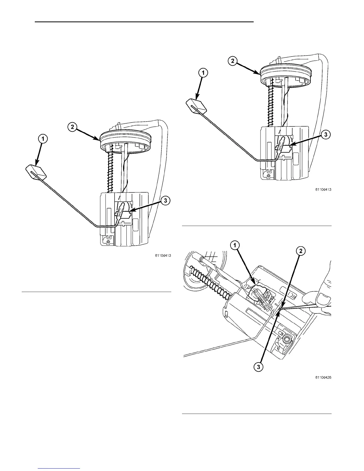
The fuel gauge sending unit (fuel level sensor) is
attached to the side of the fuel tank module (Fig. 13).
The sending unit consists of a float, an arm, and a
variable resistor track (card).
REMOVAL
The fuel level sending unit (fuel level sensor) and
float assembly is located on the side of the fuel tank
module (Fig. 14).
(1) Remove fuel tank module from fuel tank. Refer
to Fuel Tank Module Removal/Installation.
(2) Disconnect wiring from fuel tank module base
using a terminal pick / removal tool. Refer to Special
Tools in 8W, Wiring for tool part numbers.
(3) To remove sending unit from tank module, lift
on plastic locking tab (Fig. 15) while sliding sending
unit on its tracks.
INSTALLATION
(1) Connect (snap) necessary wiring into base of
fuel tank module.
(2) Position sending unit to tank module. Slide and
snap into place.
(3) Install fuel tank module. Refer to Fuel Tank
Module Removal/Installation.
Fig. 13 FUEL GAUGE SENDING UNIT
1 - FLOAT AND FLOAT ARM
2 - RUBBER GASKET (SEAL)
3 - FUEL GAUGE SENDING UNIT
Fig. 14 FUEL GAUGE SENDING UNIT
1 - FLOAT AND FLOAT ARM
2 - RUBBER GASKET (SEAL)
3 - FUEL GAUGE SENDING UNIT
Fig. 15 FUEL GAUGE SENDING UNIT R/I
1 - SENDING UNIT
2 - SMALL PUNCH OR SCREWDRIVER
3 - LOCK TAB
VA FUEL DELIVERY 14 - 15

 Loading...


