NOTE: During the measurement the snap ring (7)
(Fig. 43) must contact the upper bearing surface of
the groove in the outer multiple-disc carrier (8).
NOTE: Pay attention to sequence of discs. Place
new friction multiple-discs in ATF fluid for one hour
before installing.
(4) Insert and measure spring washer (4) (Fig. 43)
and multiple-disc pack B3 (2, 6).
(a) Put multiple-discs for multiple-disc brake B3
together in the sequence shown in the illustration
and insert individually.
(b) Using a feeler gauge, determine the play 9L9
at three points between the snap ring (7) and outer
multiple-disc (1). B3 clutch clearance should be 1.0-
1.4 mm (0.039-0.055 in.). Adjust the clearance as
necessary.
(c) Adjust with snap-ring (7), if necessary. Snap-
rings are available in thicknesses of 3.2 mm (0.126
in.), 3.5 mm (0.138 in.), 3.8 mm (0.150 in.), 4.1 mm
(0.162 in.), 4.4 mm (0.173 in.), and 4.7 mm (0.185
in.).
(5) Place intermediate plate (3) on converter hous-
ing (2) and align.
NOTE: The intermediate panel can generally be
used several times. The panel must not be coated
with sealant
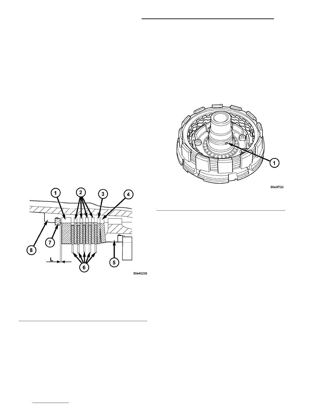
(6) Check that the K1 clutch feed hole (Fig. 44) in
the inner hub of clutch B1 is free before installing
clutch B1.
(7) Install the holding clutch B1 (5) (Fig. 45) onto
the converter housing and intermediate plate.
Installed position of clutch B1 in relation to converter
housing is specified by a plain dowel pin in clutch B1
(arrow).
(8) Install the bolts to hold clutch B1 (5) (Fig. 45)
to the converter housing.
(9) Securely tighten multiple-disc brake B1 (5) on
converter housing (2) to 10 N·m (88.5 in.lbs.).
(10) Install new torque converter hub seal (Fig. 46)
into the oil pump using Seal Installer 8902A
(11) Install new oil pump outer o-ring seal onto oil
pump (Fig. 46).
(12) Install oil pump (6) and securely tighten.
Tighten the oil pump bolts to 20 N·m (177 in.lbs.).
(13) Using grease, insert Teflon rings (7) (Fig. 47)
in the groove so that the joint remains together.
Fig. 43 Measure B3 Clutch Clearance
1 - OUTER DISC - 6.5 MM
(0.256 IN.)
5 - PISTON
2 - OUTER DISCS - 1.8 MM
(0.071 IN.)
6 - FRICTION DISCS
3 - OUTER DISCS - 1.8 MM
(0.071 IN.)
7 - SNAP-RING
4 - SPRING WASHER 8 - B3 DISC CARRIER
Fig. 44 Check K1 Feed Hole
1 - K1 CLUTCH FEED HOLE
21 - 36 AUTOMATIC TRANSMISSION - NAG1 VA
AUTOMATIC TRANSMISSION - NAG1 (Continued)

 Loading...


