CAUTION: The crankshaft bearing caps are num-
bered consecutively, beginning with the first crank-
shaft bearing cap at the front of the engine.
Attention must be paid to the way crankshaft bear-
ing caps fit.
(5) Unbolt crankshaft bearing caps (Fig. 28).
(6) Inspect crankshaft bearing caps and bolts for
wear and stretching.
(7) Remove crankshaft.
INSTALLATION
CAUTION: Oil the bearing shells before inserting
crankshaft.
CAUTION: Oil grooves in the thrust washers must
point toward the thrust collars of the crankshaft.
CAUTION: Thrust washers in the bearing cap each
have two retaining lugs as a anti-twist lock.
CAUTION: Oil thread and head contact surfaces of
bolts that retain the crankshaft bearing caps;
tighten bolts from inside to outside, beginning at
the fit bearing. Rotate crankshaft to check clear-
ance.
(1) Install crankshaft.
CAUTION: The crankshaft bearing caps are num-
bered consecutively, beginning with the first crank-
shaft bearing cap at the front of the engine.
Attention must be paid to the way the crankshaft
bearing caps fit.
(2) Install the crankshaft bearing caps. Tighten
bolts in two stages. 55N·m (40.5 lbs. ft.), then 90°.
(3) Install the pistons (Refer to 9 - ENGINE/EN-
GINE BLOCK/PISTON & CONNECTING ROD -
INSTALLATION).
(4) Install the end cover (Refer to 9 - ENGINE/EN-
GINE BLOCK/CRANKSHAFT OIL SEAL - REAR -
INSTALLATION).
(5) Install the timing case cover (Refer to 9 -
ENGINE/VALVE TIMING/TIMING BELT / CHAIN
COVER(S) - INSTALLATION).
(6) Install the engine (Refer to 9 - ENGINE -
INSTALLATION).
(7) Fill the crankcase with the correct engine oil,
to the proper level. Refer to the owners manual for
specifications.
(8) Fill the cooling system with the proper coolant,
to the proper level (Refer to 7 - COOLING/ENGINE/
COOLANT - STANDARD PROCEDURE).
(9) Connect the negative battery cable.
WARNING: USE EXTREME CAUTION WHEN THE
ENGINE IS OPERATING. DO NOT STAND IN A
DIRECT LINE WITH THE FAN. DO NOT PUT YOUR
HANDS NEAR THE PULLEYS, BELTS, OR FAN. DO
NOT WEAR LOOSE CLOTHES.
(10) Start engine and inspect for leaks. Care must
be taken to observe the fuel system warning (Refer to
14 - FUEL SYSTEM - WARNING).
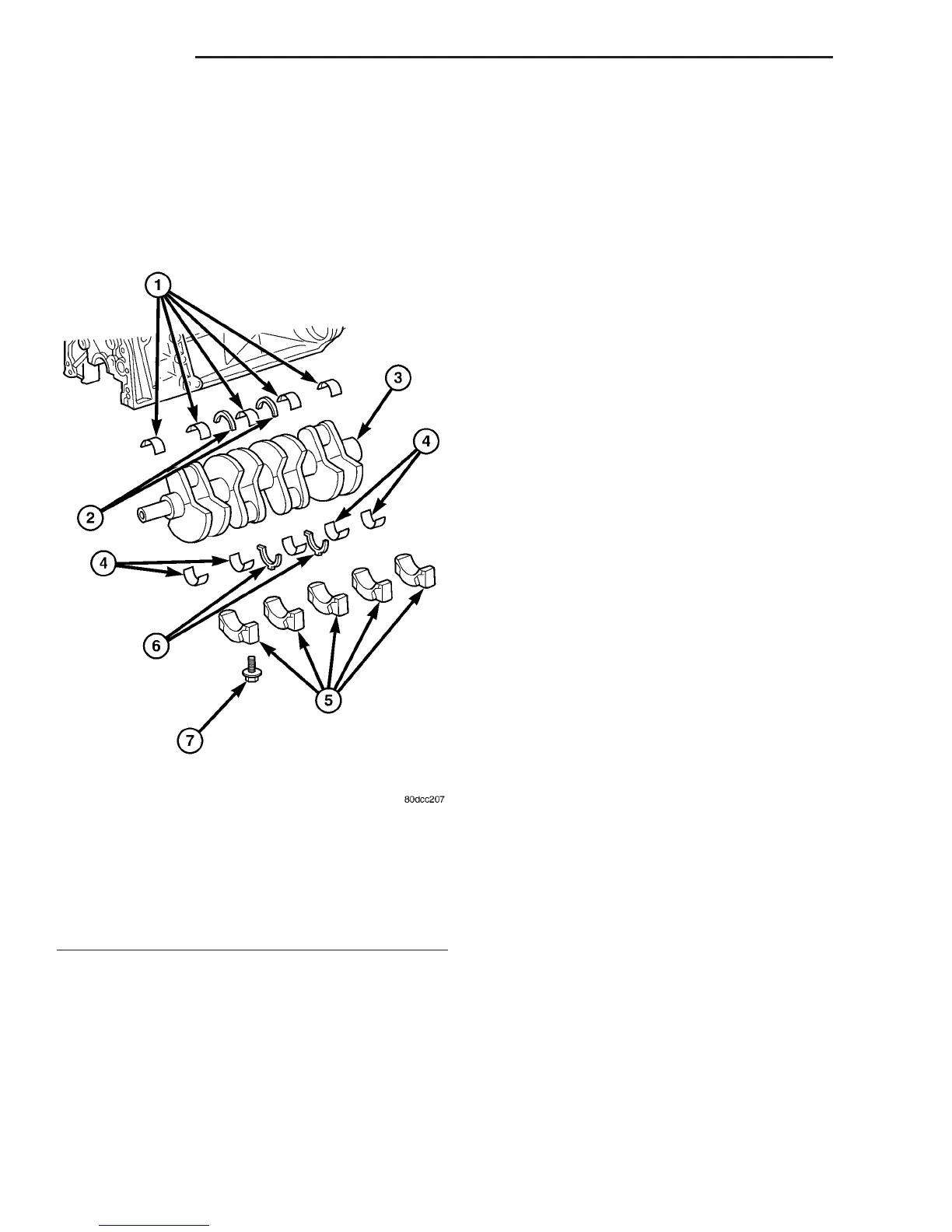
Fig. 28 CRANKSHAFT ASSEMBLY
1 - BEARING HALVES IN ENGINE BLOCK
2 - THRUST WASHERS IN ENGINE BLOCK
3 - CRANKSHAFT
4 - BEARING HALVES IN MAIN BEARING CAPS
5 - MAIN BEARING CAPS
6 - THRUST WASHERS IN MAIN BEARING CAPS
7 - MAIN BEARING BOLTS
9 - 36 ENGINE VA
CRANKSHAFT (Continued)

 Loading...


