REMOVAL
CAUTION: Do not attempt to check belt tension with
a belt tension gauge on vehicles equipped with an
automatic belt tensioner.
NOTE: The belt routing schematics are published
from the latest information available at the time of
publication. If anything differs between these sche-
matics and the Belt Routing Label, use the sche-
matics on Belt Routing Label.This label is located in
the engine compartment.
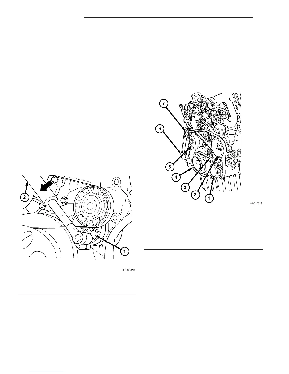
(1) A 3/8 inch square hole is provided in the auto-
matic belt tensioner. Attach a 3/8 inch drive-long
handle ratchet to this hole (Fig. 2).
(2) Rotate ratchet and tensioner assembly counter-
clockwise (as viewed from front) until tension has
been relieved from belt (Fig. 2).
(3) Remove belt from water pump pulley first.
(4) Remove belt from vehicle.
INSTALLATION
CAUTION: When installing the accessory drive belt,
the belt must be the correct length and routed cor-
rectly. If not, engine may overheat due to water
pump rotating in wrong direction.
(1) Position drive belt over all pulleys except
water pump pulley (Fig. 3).
(2) Attach a 3/8 inch ratchet to tensioner.
(3) Rotate ratchet and belt tensioner counterclock-
wise. Place belt over water pump pulley. Let ten-
sioner rotate back into place. Remove ratchet. Be
sure belt is properly seated on all pulleys.
Fig. 2 DRIVE BELT TENSIONER
1 - ACCESSORY DRIVE BELT TENSIONER
2 - RATCHET WRENCH
Fig. 3 ACCESSORY DRIVE BELT ROUTING
1 - A/C COMPRESSOR
2 - POWER STEERING
3 - DRIVE BELT TENSIONER
4 - CRANKSHAFT PULLEY
5 - WATER PUMP PULLEY
6 - GENERATOR
7 - IDLER PULLEY
7 - 8 ACCESSORY DRIVE VA
DRIVE BELTS (Continued)

 Loading...


