First Gear Engaged
The TCM monitors the activation sequence via the
speed of the input shaft, which slows down as the
frictional connection in the multiple-disc holding
clutch increases. When the speed drops to the speci-
fied level, the TCM shuts off the power to the 3-4
shift solenoid valve (10) (Fig. 19). The spring cham-
ber of the shift valve B2 (9) is depressurized and
switches downwards. This connects the line to the
opposing face of the piston B2 (6) with the pressure
holding valve (11). The pressure on the opposing face
of the piston B2 (6) drops to a residual pressure.
The working pressure (p-A) is formed and travels
via the 2-3 holding pressure shift valve, the 2-3 com-
mand valve and the ball valve (16) to multi-plate
clutch K3 (4) and via the 3-4 command valve (13) to
the end face of the 3-4 shift pressure shift valve (14).
The 3-4 shift pressure shift valve (14) is moved
against the force of the spring towards the right. At
the same time the 3-4 solenoid valve (10) is ener-
gized. This allows shift valve pressure (p-SV) to enter
the spring chamber of the shift valve B2 (9) and to
reach the end face of the 3-4 command valve (13).
The shift valve B2 (9) is held in the upper position
and the 3-4 command valve (13) switches towards the
right. At the end face of the 3-4 shift pressure shift
valve (14) the working pressure (p-A) is replaced by
shift valve pressure (p-SV).
The 3-4 command valve (13) moves to the left.
Working pressure (p-A) travels via the holding pres-
sure shift valve (12) and the 3-4 command valve (13)
to the piston of multiple-disc holding clutch B2 (5).
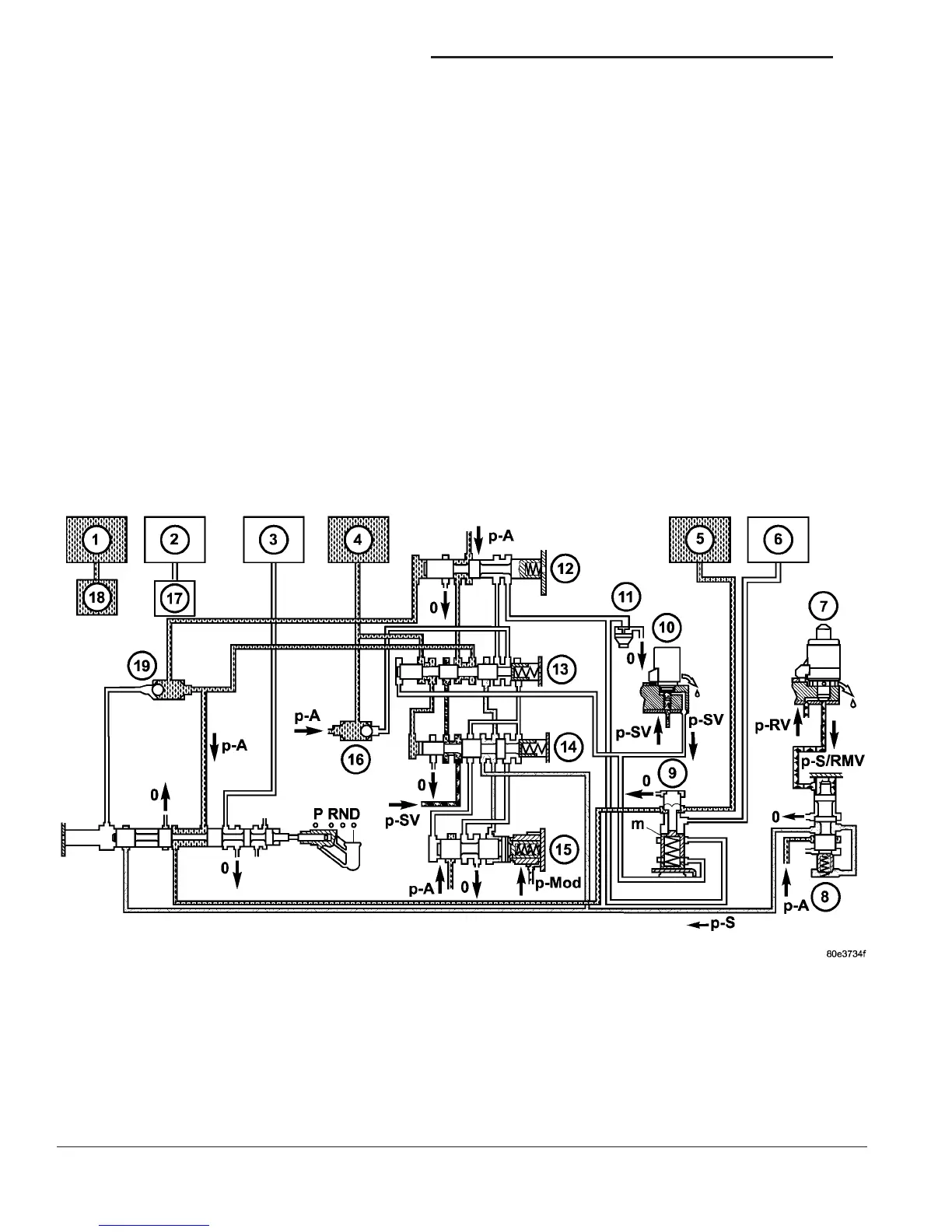
Fig. 19 First Gear Engaged
1 - HOLDING CLUTCH B1 11 - PRESSURE HOLDING VALVE
2 - DRIVING CLUTCH K1 12 - 3-4 HOLDING PRESSURE SHIFT VALVE
3 - HOLDING CLUTCH B3 13 - 3-4 COMMAND VALVE
4 - DRIVING CLUTCH K3 14 - 3-4 SHIFT PRESSURE SHIFT VALVE
5 - HOLDING CLUTCH B2 PISTON 15 - 3-4 OVERLAP REGULATING VALVE
6 - HOLDING CLUTCH B2 PISTON OPPOSING FACE 16 - BALL VALVE
7 - SHIFT PRESSURE REGULATING SOLENOID 17 - 1-2/4-5 COMMAND VALVE
8 - SHIFT PRESSURE REGULATING VALVE 18 - 1-2/4-5 COMMAND VALVE
9 - SHIFT VALVE B2 19 - BALL VALVE
10 - 3-4 SHIFT SOLENOID
21 - 22 AUTOMATIC TRANSMISSION - NAG1 VA
AUTOMATIC TRANSMISSION - NAG1 (Continued)

 Loading...


