(1) Reconnect and latch the vehicle wire harness
connector for the ACM to the ACM connector recep-
tacle located on the left facing side of the module
(Fig. 12).
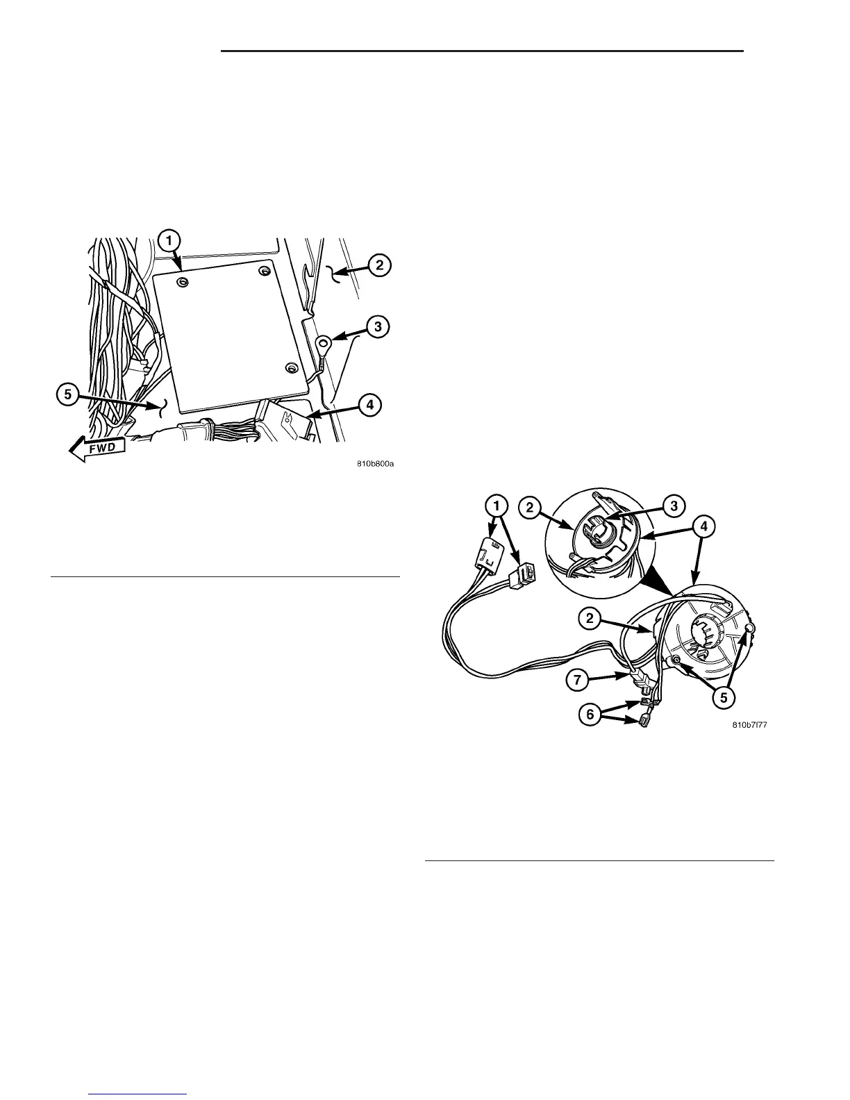
(2) Carefully position the ACM cover base plate
onto the mounting bracket that is welded onto the
floor panel under the driver side front seat (Fig. 13).
(3) Carefully position the ACM onto the ACM cover
base plate. When the ACM is correctly positioned, the
three ACM mounting tabs will be aligned with the
holes in the cover base plate and the mounting
bracket, and the orientation arrow on the ACM label
will be pointed forward in the vehicle.
(4) Install and tighten the three screws that secure
the ACM to the mounting bracket that is welded onto
the floor panel within the driver side front seat riser.
Be certain that the ground eyelet terminal is
installed under the screw for the left rear mounting
tab. Tighten the screws to 12 N·m (105 in. lbs.).
(5) Position the ACM cover over the ACM and
press it down firmly and evenly until it snaps into
position over the ACM cover base plate (Fig. 11).
(6) Position the control module bracket onto the
top of the driver side seat riser (Fig. 10).
(7) Install and tighten the two screws that secure
the control module bracket to the top of the seat riser
under the driver side front seat. Tighten the screws
to 2 N·m (18 in. lbs.).
(8) Position the cover panel onto the top of the
driver side seat riser (Fig. 9).
(9) Install and tighten the two screws that secure
the cover panel to the top of the seat riser under the
driver side front seat. Tighten the screws to 2 N·m
(18 in. lbs.).
(10) Move the driver side front seat back to its
driving position.
(11) Do not reconnect the battery negative cable at
this time. The supplemental restraint system verifi-
cation test procedure should be performed following
service of any supplemental restraint system compo-
nent. (Refer to 8 - ELECTRICAL/RESTRAINTS -
STANDARD PROCEDURE - VERIFICATION TEST).
NOTE: If the Airbag Control Module (ACM) has been
replaced with a new unit, it will be necessary to ini-
tialize the new ACM. In order to function properly,
the ACM must be programmed for the correct stan-
dard and optional supplemental restraint system
components installed in the vehicle. To initialize the
ACM, a DRBIIIT scan tool is required. Refer to the
appropriate diagnostic information.
CLOCKSPRING
DESCRIPTION
The clockspring assembly is secured with two
screws onto the multi-function switch housing near
the top of the steering column directly below the
steering wheel (Fig. 14). The clockspring consists of a
flat, round molded plastic case that contains a spool-
like molded plastic rotor with a large exposed hub
covering the entire upper surface of the case. The
rotor hub has a large center hole that is internally
ribbed to engage splines on the upper steering col-
umn shaft, and two small clearance holes that pro-
Fig. 13 ACM Cover Base Plate
1 - BASE PLATE
2 - SEAT RISER
3 - GROUND EYELET TERMINAL
4 - ACM CONNECTOR
5 - FLOOR PANEL
Fig. 14 Clockspring
1 - PIGTAIL WIRE CONNECTOR (2)
2 - CASE
3 - CANCEL CAM
4 - ROTOR
5 - SCREW (2)
6 - HORN SWITCH CONNECTOR (2)
7 - AIRBAG CONNECTOR
8O - 12 RESTRAINTS VA
AIRBAG CONTROL MODULE (Continued)

 Loading...


