(3) Disconnect the front lamp unit wire harness
connector from the low beam headlamp bulb base
(Fig. 36).
(4) Disengage the low beam headlamp bulb
retainer by pushing it slightly toward the front lamp
unit housing and downward from the bulb base, then
pivot the retainer off of the bulb base.
(5) Remove the low beam headlamp bulb from the
integral bulb holder on the front lamp unit reflector.
INSTALLATION
(1) Position the low beam headlamp bulb into the
integral bulb holder on the front lamp unit reflector.
Be certain that the lugs on the bulb base are
engaged in the recesses of the bulb holder (Fig. 36).
(2) Engage the low beam headlamp bulb retainer
by pivoting it over the bulb base, pressing it slightly
toward the front lamp unit housing and upward
toward the side of the bulb base.
(3) Reconnect the front lamp unit wire harness
connector to the low beam headlamp bulb base.
(4) Position the front lamp unit rear cover onto the
lamp housing and engage the retainers over each
side of the cover to secure it (Fig. 35).
(5) Reconnect the battery negative cable.
MULTI-FUNCTION SWITCH
REMOVAL
WARNING: ON VEHICLES EQUIPPED WITH AIR-
BAGS, DISABLE THE SUPPLEMENTAL RESTRAINT
SYSTEM BEFORE ATTEMPTING ANY STEERING
WHEEL, STEERING COLUMN, DRIVER AIRBAG,
PASSENGER AIRBAG, SEAT BELT TENSIONER, OR
INSTRUMENT PANEL COMPONENT DIAGNOSIS OR
SERVICE. DISCONNECT AND ISOLATE THE BAT-
TERY NEGATIVE (GROUND) CABLE, THEN WAIT
TWO MINUTES FOR THE SYSTEM CAPACITOR TO
DISCHARGE BEFORE PERFORMING FURTHER
DIAGNOSIS OR SERVICE. THIS IS THE ONLY SURE
WAY TO DISABLE THE SUPPLEMENTAL
RESTRAINT SYSTEM. FAILURE TO TAKE THE
PROPER PRECAUTIONS COULD RESULT IN ACCI-
DENTAL AIRBAG DEPLOYMENT AND POSSIBLE
PERSONAL INJURY.
(1) Disconnect and isolate the battery negative
cable.
(2) Remove the fuse block from the underside of
the steering column. (Refer to 8 - ELECTRICAL/
POWER DISTRIBUTION/FUSE BLOCK - REMOV-
AL).
(3) Remove the clockspring from the steering col-
umn. (Refer to 8 - ELECTRICAL/RESTRAINTS/
CLOCKSPRING - REMOVAL).
(4) Remove the two screws that secure the upper
shroud to the top of the multi-function switch (Fig.
37).
(5) Remove the upper shroud from the top of the
multi-function switch.
(6) Remove the two screws that secure the multi-
function switch to the steering column.
(7) Remove the multi-function switch from the
steering column.
(8) Remove the speed control switch from the back
of the multi-function switch. (Refer to 8 - ELECTRI-
CAL/SPEED CONTROL/SWITCH - REMOVAL).
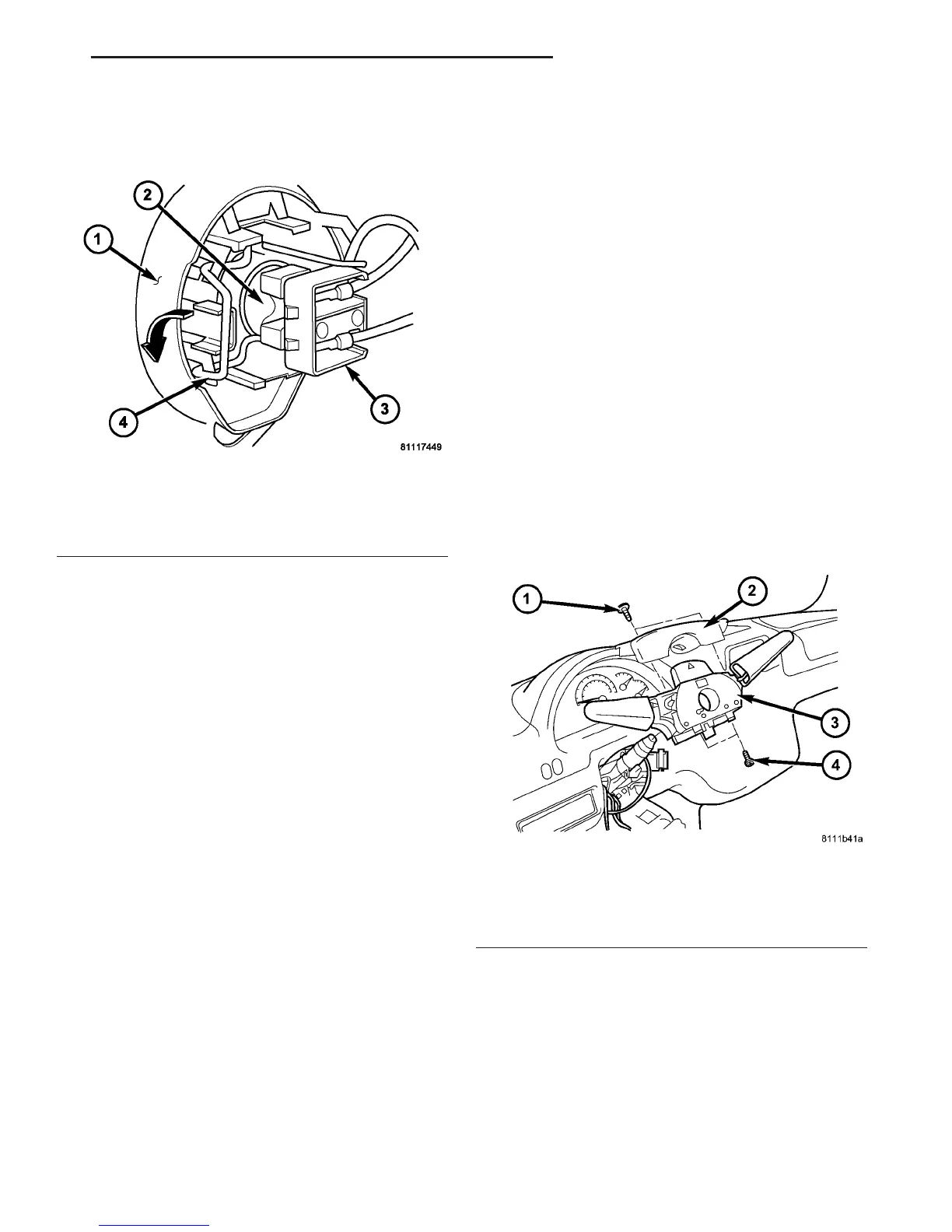
Fig. 36 Low Beam Headlamp Bulb Remove/Install
1 - LAMP HOUSING
2 - BULB BASE
3 - CONNECTOR
4 - BULB RETAINER
Fig. 37 Multi-Function Switch Remove/Install
1 - SCREW (2)
2 - UPPER SHROUD
3 - SWITCH
4 - SCREW (2)
VA LAMPS/LIGHTING - EXTERIOR 8L - 19
LOW BEAM HEADLAMP BULB (Continued)

 Loading...


