(2) Tighten door fasteners to 10 N·m (89 in. lbs.).
(3) Install bracket onto check and install bracket
bolt/nut.
(4) Tighten bracket bolt/nut to 6 N·m (53 in. lbs.).
(5) Install check bracket onto a-pillar.
(6) Apply Loctitet 243 sealant check strap bolts
and install bolts.
(7) Tighten the M8 bolts to 35 N·m (26 ft. lbs.) or
tighten the M6 bolts to 10 N·m (89 in. lbs.).
(8) Install trim panel. (Refer to 23 - BODY/DOOR -
FRONT/TRIM PANEL - INSTALLATION)
(9) Connect battery negative cable.
DOOR
REMOVAL
(1) Disconnect and isolate battery negative cable.
(2) Remove mirror. (Refer to 23 - BODY/EXTERI-
OR/SIDE VIEW MIRROR - REMOVAL)
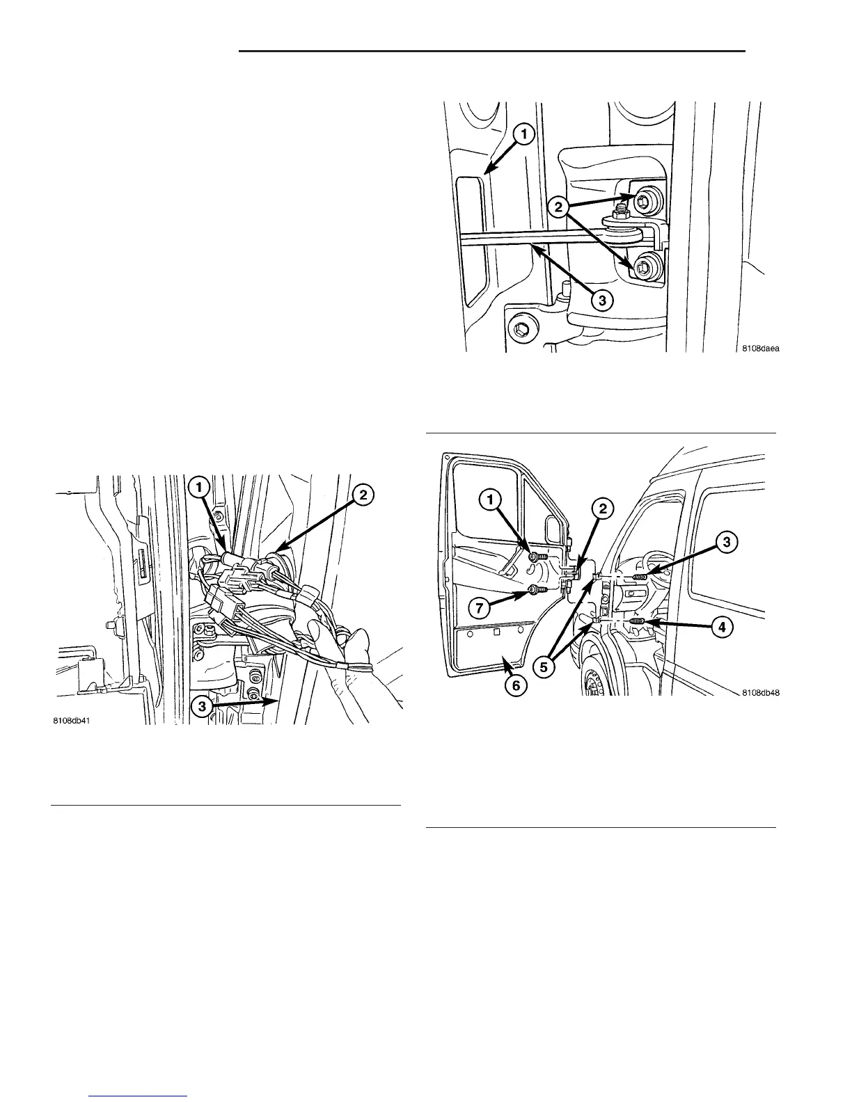
(3) Position aside the wiring boot and disconnect
the electrical connectors. (Fig. 3)
(4) Remove the bolts and disconnect the door check
from the a-pillar. (Fig. 4)
(5) Support door with a suitable device.
(6) Loosen the hinge set screws. (Fig. 5)
(7) Remove door by lifting off hinge pins.
INSTALLATION
(1) Slide door into hinges.
(2) Install set screws.
(3) Install check bracket onto a-pillar.
(4) Apply Loctitet 243 sealant check strap bolts
and install bolts.
(5) Tighten the M8 bolts to 35 N·m (26 ft. lbs.) or
tighten the M6 bolts to 10 N·m (89 in. lbs.).
(6) Connect all door electrical connectors and posi-
tion boot back.
(7) Install mirror. (Refer to 23 - BODY/EXTERI-
OR/SIDE VIEW MIRROR - INSTALLATION)
(8) Adjust door if required. (Refer to 23 - BODY/
DOOR - FRONT/DOOR - ADJUSTMENTS)
(9) Connect battery negative cable.
Fig. 3 ELECTRICAL CONNECTORS
1 - ELECTRICAL CONNECTORS
2 - BOOT
3 - DOOR
Fig. 4 FRONT DOOR CHECK - BODY
1 - DOOR
2 - A-PILLAR BOLTS
3 - DOOR CHECK
Fig. 5 FRONT DOOR
1 - UPPER CHECK BOLT
2 - DOOR CHECK
3 - UPPER HINGE SET SCREW
4 - LOWER HINGE SET SCREW
5 - HINGE RECEIVERS
6 - DOOR
7 - LOWER CHECK BOLT
23 - 14 DOOR - FRONT VA
CHECK (Continued)

 Loading...


