8W-91 CONNECTOR/GROUND/SPLICE LOCATION
TABLE OF CONTENTS
page
CONNECTOR/GROUND/SPLICE LOCATION
DESCRIPTION ..........................1
CONNECTOR/GROUND/SPLICE
LOCATION
DESCRIPTION
This section provides illustrations identifying con-
nector, ground, and splice locations in the vehicle.
Connector, ground, and splice indexes are provided.
Use the wiring diagrams in each section for connec-
tor, ground, and splice identification. Refer to the
appropriate index for the proper figure number. For
items that are not shown in this section N/S is placed
in the Fig. column.
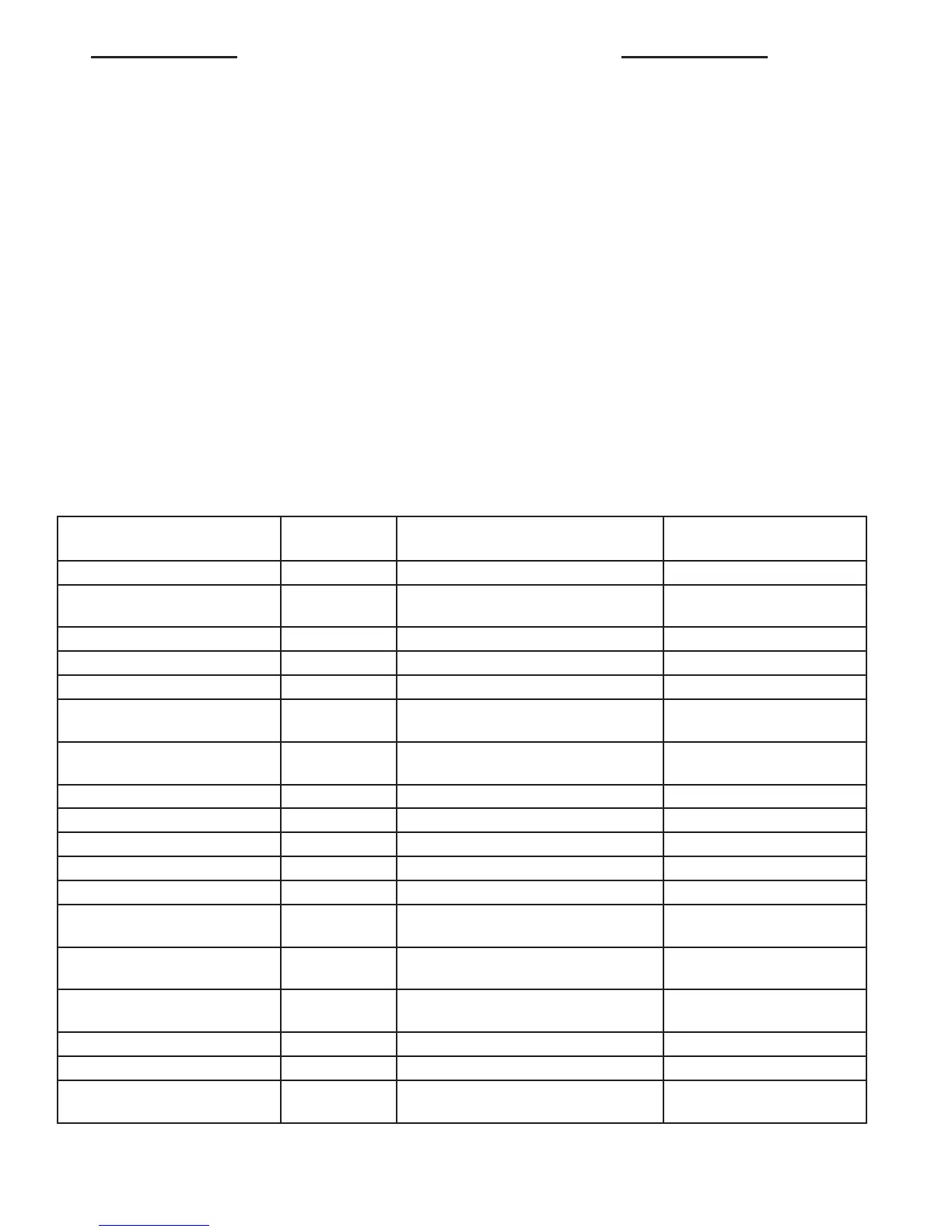
CONNECTORS
CONNECTOR NAME/
NUMBER
COLOR LOCATION FIG.
A/C Auxiliary Fan Engine Compartment N/S
A/C Auxiliary Fan Relay (In
Relay Block)
Under Driver Seat N/S
A/C Control Module-Roof Instrument Panel N/S
A/C Fan Switch Instrument Panel N/S
A/C Switch - Roof Instrument Panel N/S
Accelerator Pedal Position
Sensor
On Gas Pedal 14
Air Outlet Temperature
Sensor
Engine Compartment (Right Rear) 5,15
Airbag Control Module Under Driver Seat 10,16,18
Airbag Squib-Driver Steering Wheel 10
Airbag Squib-Passenger Instrument Panel (Passenger Side) N/S
Ambient Temperature Sensor Front Engine Compartment 2,15
Ash Receiver Lamp In Ash Tray N/S
Automatic Temperature
Control Module C1
Instrument Panel N/S
Automatic Temperature
Control Module C2
Instrument Panel N/S
Auxiliary Heater Relay (In
Relay Block)
Under Driver Seat N/S
Auxiliary Heater Switch Instrument Panel N/S
Battery Relay-Auxiliary Engine Compartment N/S
Blower Motor Resistor Block Underhood Right (To The
Instrument Panel)
4
VA 8W-91 CONNECTOR/GROUND/SPLICE LOCATION 8W - 91 - 1

 Loading...


