Injector closed (with high pressure applied)
With the injector closed (at-rest state), the solenoid
valve is not energized and is therefore closed. With
the bleed orifice closed, the valve spring forces the
armature’s ball onto the bleed-orifice seat. The rail’s
high pressure build up in the valve control chamber,
and the same pressure is also present in the nozzle’s
chamber volume. The rail pressure applied at the
control plunger’s end face, together with the force of
the nozzle spring, maintain the nozzle in the closed
position against the opening forces applied to its
pressure stage (Fig. 8).
Injector opens (start of injection)
The solenoid valve is energized with the pickup
current which serves to ensure that it open quickly.
The force exerted by the triggered solenoid now
exceeds that of the valve spring and the armature
opens the bleed orifice. Almost immediately, the high-
level pick-up current is reduced to the lower holding
current required for the electromagnet. This is possi-
ble due to the magnetic circuit’s air gap now being
smaller. When the bleed orifice opens, fuel can flow
from the valve control chamber into the cavity situ-
ated above it, and from there via the fuel return to
the tank. The bleed orifice prevents complete pres-
sure balance, and the pressure in the valve control
chamber sinks as a result. This leads to the pressure
in the valve-control chamber being lower than that in
the nozzle’s chamber volume which is still at the
same pressure level as the rail. The reduced pressure
in the valve-control chamber causes a reduction in
the force exerted on the control plunger, the nozzle
needle open as a result, and injection starts (Fig. 8).
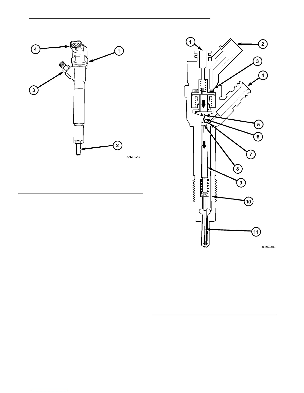
Fig. 7 FUEL INJECTOR
1 - FUEL INJECTOR
2 - NOZZLE
3 - FUEL INLET FITTING
4 - ELECTRICAL CONNECTION
Fig. 8 INJECTOR COMPONENTS
1 - INJECTOR CLOSED (AT-REST STATUS)
2 - ELECTRICAL CONNECTION
3 - TRIGGERING ELEMENT (SOLENOID VALVE)
4 - FUEL INLET (HIGH PRESSURE) FROM THE RAIL
5 - VALVE BALL
6 - BLEED ORIFICE
7 - FEED ORIFICE
8 - VALVE CONTROL CHAMBER
9 - VALVE CONTROL PLUNGER
10 - FEED PASSAGE TO THE NOZZLE
11 - NOZZLE NEEDLE
VA FUEL INJECTION 14 - 21
FUEL INJECTOR (Continued)

 Loading...


