HIGH PRESSURE SIDE
A. Filling the piston: The piston is moved down
as a result of the piston spring. The fuel supplied by
the fuel delivery pump flows along the ring passage,
the valve disk and the valve spring into the cylinder.
The ball valve prevents the fuel from being able to
flow back from the high pressure passage.
B. Producing high pressure: The piston is
moved up by the rising eccentric shaft and the fuel is
thus compressed. The valve disk shuts off the deliv-
ery volume to the fuel feed. Once the fuel pressure in
the cylinder rises beyond the pressure which exists
in the high pressure circuit, the ball valve opens and
the fuel is pumped into the high pressure circuit.
C. Fuel Temperature Regulation The ECM can
Interrupt the fuel high pressure delivery of one of the
pump elements in the particle load range in order to
reduce the power required for driving the high pres-
sure pump so as to reduce the fuel temperature. The
pump element is switched off if the fuel temperature
is excessively high (above 278°, 120 bar).
OPERATION - LOW PRESSURE PUMP
The low pressure pump draws fuel from tank
through fuel filter and supplies the high pressure
pump. Fuel pressure at starter speed is 0.4 to 1.5 bar
(6 to 22 psi.). A fuel pressure of 2.0 to 2.5 bar (29 to
36 psi.) is reached at idle speed. Fuel pressure is lim-
ited to 3.5 bar ± .5 bar (51 psi. ± 7 psi) by the valve
in the fuel delivery pump. This valve opens by over
coming a spring force and allows excessive fuel to
flow to the intake side of the low pressure pump.
This diverted fuel flows into the return flow pipe
through the fuel cooler back to the tank. As a result
of this circulation, the fuel always remains relatively
cool.
REMOVAL
REMOVAL - HIGH PRESSURE PUMP
(Refer to 14 - FUEL SYSTEM - WARNING)
(1) Disconnect negative battery cable.
(2) Remove viscous fan clutch (Refer to 7 - COOL-
ING/ENGINE/FAN DRIVE VISCOUS CLUTCH -
REMOVAL).
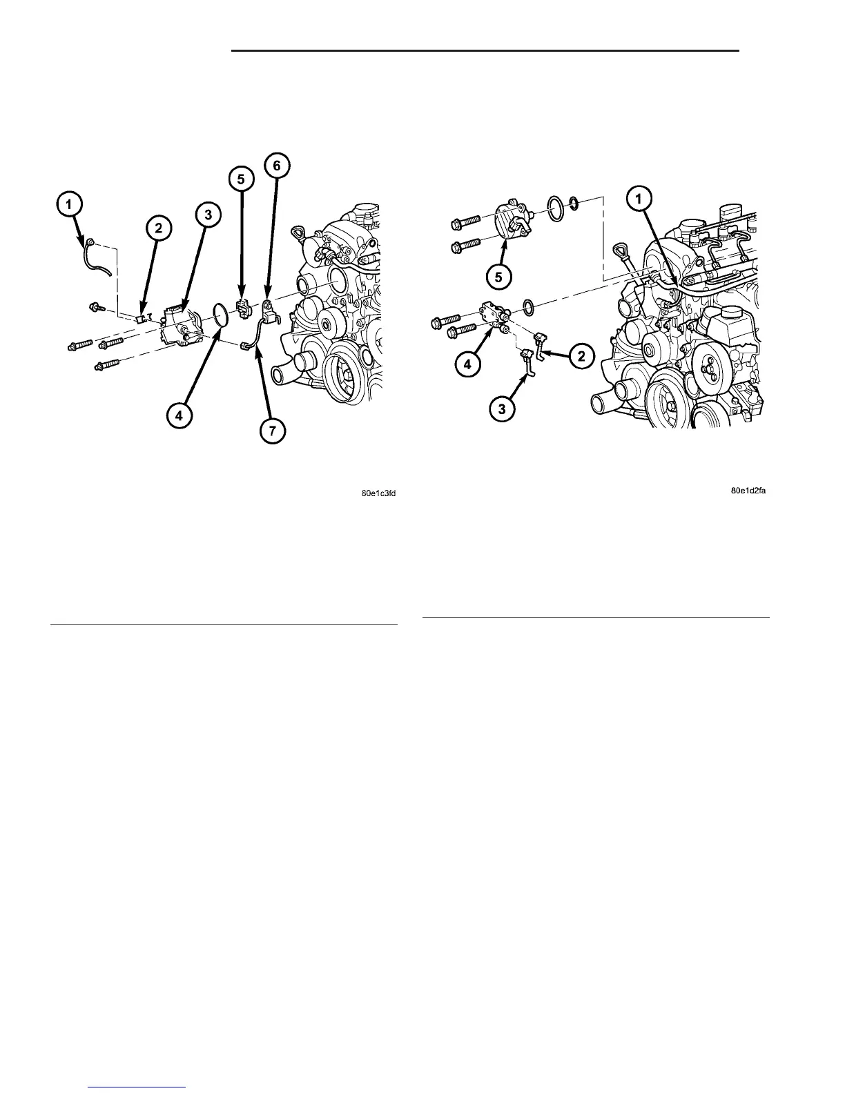
Fig. 3 HIGH PRESSURE PUMP
1 - FUEL RETURN LINE
2 - FUEL LINE BRACKET
3 - HIGH PRESSURE PUMP
4 - O-RING
5 - PUMP DRIVE
6 - FUEL LINE BRACKET
7 - HIGH PRESSURE FUEL LINE FROM PUMP TO FUEL RAIL
Fig. 4 VACUUM PUMP AND LOW PRESSURE FUEL
PUMP ASSEMBLIES
1 - VACUUM LINE
2 - FUEL OUTLET LINE
3 - FUEL FEED LINE
4 - LOW PRESSURE FUEL PUMP
5 - VACUUM PUMP
14 - 8 FUEL DELIVERY VA
FUEL PUMP (Continued)

 Loading...


