PISTON RINGS
STANDARD PROCEDURE - PISTON RING
FITTING
(1) Carefully clean the carbon from all ring
grooves. Oil drain openings in the oil ring groove and
pin boss must be clear. DO NOT remove metal from
the grooves or lands. This will change ring-to-groove
clearances and will damage the ring-to-land seating.
(2) Be sure the piston ring grooves are free of
nicks and burrs.
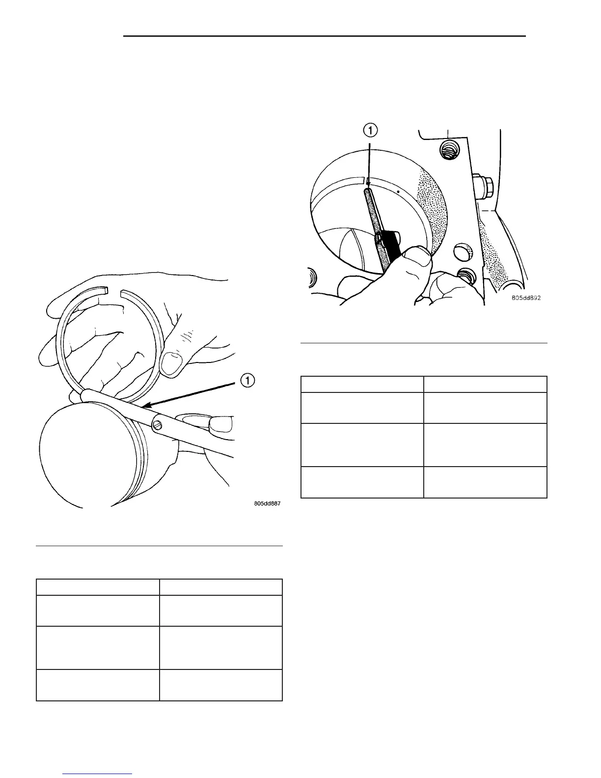
(3) Measure the ring side clearance with a feeler
gauge fitted snugly between the ring land and ring
(Fig. 39). Rotate the ring in the groove. It must move
freely around circumference of the groove.
RING SIDE CLEARANCE CHART
ITEM SPECIFICATION
Top Compression Ring 0.012 - 0.016 mm
(0.0047 - 0.0063 in.)
Second Compression
Ring
0.05 - 0.09 mm
(0.0019 - 0.0035 in.)
Oil Control Ring 0.03 - 0.07 mm
(0.0011 - 0.0027 in.)
(4) Place ring in the cylinder bore and push down
with inverted piston to position near lower end of the
ring travel. Measure ring gap with a feeler gauge fit-
ting snugly between ring ends (Fig. 40).
RING GAP MEASUREMENT CHART
ITEM SPECIFICATION
Top Compression Ring 0.229 - 0.610 mm
(0.0090 - 0.0240 in.)
Second Compression
Ring
0.483 - 0.965 mm
(0.0190 - 0.080 in.)
Oil Control Ring 0.254 - 1.500 mm
(0.010 - 0.060 in.)
(5) The oil control rings are symmetrical, and can
be installed with either side up. It is not necessary to
use a tool to install the upper and lower rails. Insert
oil rail spacer first, then side rails.
(6) Using a ring expander, install compression
rings with manufactures designation pointing toward
piston crown (Fig. 41).
Ring Gap Orientation
• Position the gaps on the piston as shown (Fig.
42).
• Oil spacer - Gap on center line of piston skirt.
• Oil rails - gap 180° apart on centerline of piston
pin bore.
• No. 2 Compression ring - Gap 120° from top oil
rail gap.
Fig. 39 Measuring Piston Ring Side Clearance
1 - FEELER GAUGE
Fig. 40 Ring
1 - FEELER GAUGE
9 - 46 ENGINE VA

 Loading...


