CRANKSHAFT
STANDARD PROCEDURE - MEASURE
CRANKSHAFT AND BLOCK JOURNALS
NOTE: After any bearing damage occurred, remove
all debris which is present in the main oil gallery,
connecting rod bores, and in the crankshaft and oil
galleries. Include removal of the inserting steel ball
of the main oil gallery before cleaning.
(1) Remove crankshaft (Refer to 9 - ENGINE/EN-
GINE BLOCK/CRANKSHAFT - REMOVAL).
(2) Clean all engine parts thoroughly.
CAUTION: After bearing has damage has occurred,
replace connecting rods which have suffered over-
heating because of bearing damage. The connect-
ing rod must not have any cross scores and
notches.
(3) Inspect connecting rod. If damage is present,
inspect crankshaft, replace as necessary.
(4) Inspect crankcase.
(5) Inspect standard size of crankshaft bearing
shells.
(6) Inspect crankshaft bearing cap.
(7) Mount crankshaft radially.
(8) Inspect crankshaft bearing play.
NOTE: Radial mounting of the main bearings of
standard size crankshaft is possible by assigning
the color-coded bearing shells.
ASSIGN CRANKSHAFT BEARING SHELLS
The oil pan rail of the cylinder block is marked
with chisel punches indicating what bearing shell are
used.
(9) Assign crankshaft bearing shells.
(10) Mount crankshaft axially.
(11) Inspect crankshaft bearing play.
REMOVAL
(1) Remove engine (Refer to 9 - ENGINE -
REMOVAL).
(2) Remove timing case cover (Refer to 9 -
ENGINE/VALVE TIMING/TIMING BELT / CHAIN
COVER(S) - REMOVAL)
(3) Remove end cover.(Refer to 9 - ENGINE/EN-
GINE BLOCK/CRANKSHAFT OIL SEAL - REAR -
REMOVAL).
(4) Remove pistons (Refer to 9 - ENGINE/ENGINE
BLOCK/PISTON & CONNECTING ROD - REMOV-
AL).
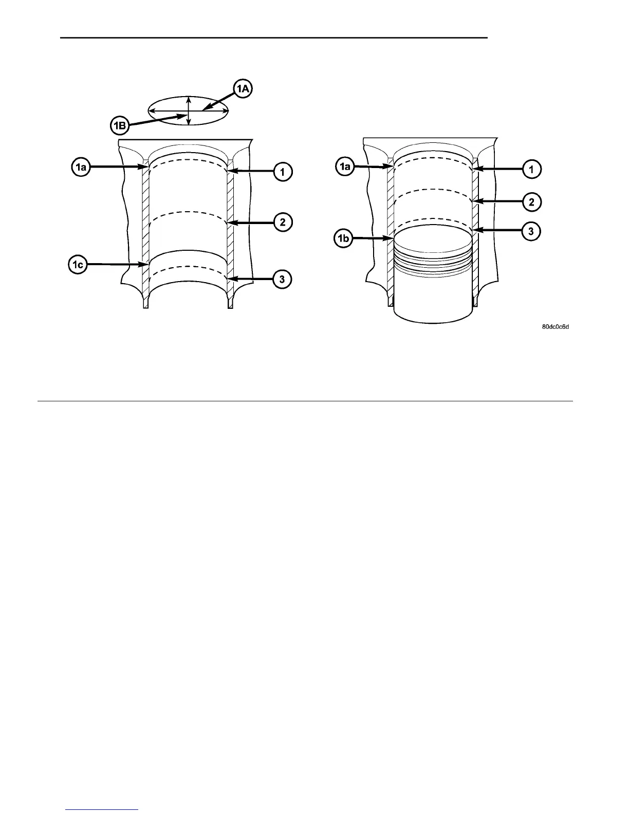
Fig. 27 MEASURING CYLINDER BORES
1 - MEASURING POINT OF CYLINDER BORE
2 - MEASURING POINT OF CYLINDER BORE
3 - MEASURING POINT OF CYLINDER BORE
1a - UPPER REVERSAL POINT OF #1 PISTON RING
1b - BOTTOM DEAD CENTER OF PISTON
1c - BOTTOM REVERSAL POINT OF OIL SCRAPER RING
1A - LONGITUDINAL DIRECTION
1B - TRANSVERSE PDIRECTION
VA ENGINE 9 - 35
ENGINE BLOCK (Continued)

 Loading...


