switch housing and behind the fuse block underneath
the steering column (Fig. 17).
(5) Reinstall the steering column opening cover
onto the instrument panel. (Refer to 23 - BODY/IN-
STRUMENT PANEL/STEERING COLUMN OPEN-
ING COVER - INSTALLATION).
(6) Reinstall the steering wheel onto the steering
column. (Refer to 19 - STEERING/COLUMN/STEER-
ING WHEEL - INSTALLATION).
(7) Reconnect the clockspring upper pigtail wire
connectors to the terminals of the horn switch
located in the hub cavity of the steering wheel.
(8) Reinstall the driver airbag onto the steering
wheel. (Refer to 8 - ELECTRICAL/RESTRAINTS/
DRIVER AIRBAG - INSTALLATION).
DRIVER AIRBAG
DESCRIPTION
The color-keyed, injection molded, thermoplastic
driver airbag protective trim cover is the most visible
part of the driver airbag (Fig. 18). The driver airbag
is located in the center of the steering wheel, where
it is secured with two screws to the armature of the
horn switch within the hub cavity of the four-spoke
steering wheel. Concealed beneath the driver airbag
trim cover are the folded airbag cushion, the airbag
cushion retainer, the airbag housing, the airbag infla-
tor, and the retainers that secure the inflator to the
airbag housing (Fig. 19). The airbag cushion, hous-
ing, and inflator are secured within an integral
receptacle molded into the back of the trim cover.
The airbag used in this model is a Next Genera-
tion-type that complies with revised federal airbag
standards to deploy with less force than those used
in some prior models. A radial deploying fabric cush-
ion with internal tethers is used. The airbag inflator
is a solid fuel, pyrotechnic-type unit with four studs
and is secured by four hex nuts to four studs on the
airbag cushion retainer ring to the back of the
stamped metal airbag housing. A keyed connector
receptacle on the driver airbag inflator connects the
inflator initiator to the vehicle electrical system
through a yellow-jacketed, two-wire pigtail harness of
the clockspring.
The driver airbag and trim cover unit cannot be
repaired, and must be replaced if deployed, faulty, or
in any way damaged.
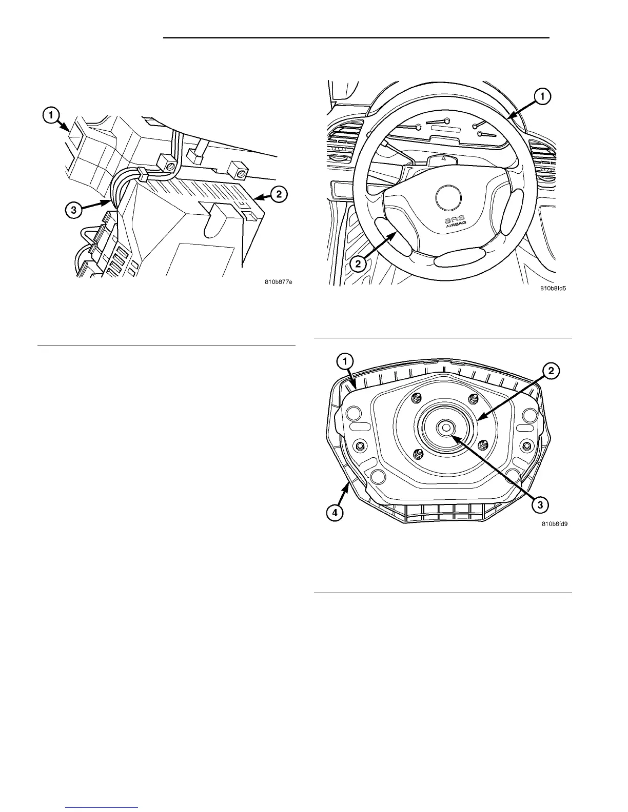
Fig. 17 Clockspring Pigtail Routing
1 - MULTI-FUNCTION SWITCH
2 - FUSE BLOCK
3 - CLOCKSPRING LOWER PIGTAILS (2)
Fig. 18 Driver Airbag Trim Cover
1 - STEERING WHEEL
2 - TRIM COVER
Fig. 19 Driver Airbag Housing
1 - HOUSING
2 - INFLATOR
3 - CONNECTOR RECEPTACLE
4 - TRIM COVER
8O - 16 RESTRAINTS VA
CLOCKSPRING (Continued)

 Loading...


